I’m always amazed with EditEd4TV’s ability to analyze what should be a simple signal path. He literally blows my mind when it comes to this technical stuff. And I find myself reading it about 5 times before some part of it actually sinks in. And of course the real fun comes in figuring out just “what” musically you can do with this information. So not to disappoint, Ed is back with a great tutorial on the inner workings of Thor’s Shaper feature, and more specifically the “Sine” wave inside the shaper. If you feel brave enough, my young paduan learners, then venture forward where quite honestly no man has gone before. . .
Download the project files here: EditEd4TV_ThorShaperFiles. They contain an Excel spreadsheet with the settings for various sine wave values/positions, as well as Ed’s 4 source cross-fader which was designed using the Shaper’s Sine wave. Quite a brilliant design idea.
Thor’s Shaper can produce a number of interesting distortion effects when processing an audio signal from any of the three oscillator slots, but one of the more arcane features of the shaper is the processing of CV data. In this setup I’m routing the mod wheel data, 0-127, into Filter 1, which is in bypass mode (no filter), which is then routed into the Shaper, set in the sine wave preset. So that you don’t bypass the learning here, I’m not providing the patch, as it’s better to get your hands dirty and learn the hard way, so let’s make this specific patch before moving on:
Processing CV data through Thor’s Shaper
- First, create a Thor device and initialize the preset if necessary.
- Next, set filter slot 1 to bypass.
- Deactivate oscillator 1 routing to filter 1, and activate it for filter 2.
- Activate the routing button to send filter 2 to the amp (it’s directly below the Shaper’s Drive knob).
- At this point, if you set the Step Sequencer to Repeat mode, and press the Run button, you should hear a basic repeating pulse coming from oscillator 1. If you don’t hear this, go back and check your settings before moving forward.
- Next, in the Step Sequencer, move the Steps knob on the far right so that we have only 1 step. For this single step, set the gate length from 75% to 100%. At this point, if you press the Run button you should hear a single pulse that drops in volume. Change the oscillator type from sawtooth to a sine wave for a more pleasant tone, and raise the amp envelope sustain level from -21.8 dB (default) to full 0.0 dB. At this point you should hear a steady sine wave tone. Again, if you don’t hear this, go back and check your settings before moving forward.
- In the Modulation Bus Routing Section, make the following assignment:
Source -> Amount -> Destination -> Amount -> Scale
Mod Wheel -> 100 -> Oscillator 1 pitch
- At this stage, if you raise the mod wheel you should hear the pitch rise and fall as you move the mod wheel – this is direct control with essentially linear control/results. Change this amount value to 0 for the time being.
- Now activate the Shaper, change the mode to Sine, and in the Modulation Bus Routing Section, make the following assignments:
Source -> Amount -> Destination -> Amount -> Scale
Mod Wheel -> 100 -> Filter 1 Audio Input
Shaper -> 100 -> Oscillator 1 pitch
- At this stage, if you raise the mod wheel you should hear the pitch first rise, but then suddenly begin to fall. This is the sine wave of the Shaper controlling oscillator pitch. At the default of 37, you’re hearing just a portion of what’s available in this shaper setting. For a nearly perfect full sine wave cycle, set the Shaper Drive value to 50. If you listen carefully to the results, you’ll hear that with the Mod Wheel at full 127, the pitch is slightly higher than with the Mod Wheel at 0. To verify that things are off a bit, create an Analog Oscillator in oscillator slot 2, set the type to sine wave, and engage the routing button to filter 2 for oscillator 2. With the Mod Wheel at 0, you’ll hear the two oscillators in perfect sync, but with the Mod Wheel at 127, they’re off a bit. To trim this, in the Modulation Bus Routing Section, modify the previous assignment to this:
Source -> Amount -> Destination -> Amount -> Scale
Mod Wheel -> 100 -> Filter 1 Audio Input -> 2 -> Rotary 2
- You should hear Oscillator 1 pitch drop a bit. Now turn up Rotary 2 and you’ll hear the pitch rise to meet up with Oscillator 2, which is unaffected by the Mod Wheel. A Rotary 2 setting of 62 is nearly perfect. Sweep the Mod Wheel from 0 to 127 and you should hear the full sine wave cycle, landing nearly perfectly with both oscillators showing the match.
Through painstaking research, I went through and found the settings for various sine wave values/positions. You can view the chart in the Project Files download (above).
To plot out a sine wave in Excel, the magic number we’re working with is 20.21267. The A column serves as our Mod Wheel range. In the B column we find the result of a formula which works with the Mod Wheel values and multiples of the magic 20.21267 value.
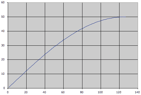
When you open the spreadsheet you’re seeing the 1/4 cycle output in the chart:

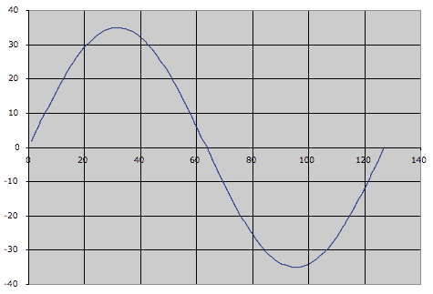
Copy the E5 to I5 range and paste into the E22 to I22 range and you’ll see the result in the chart:

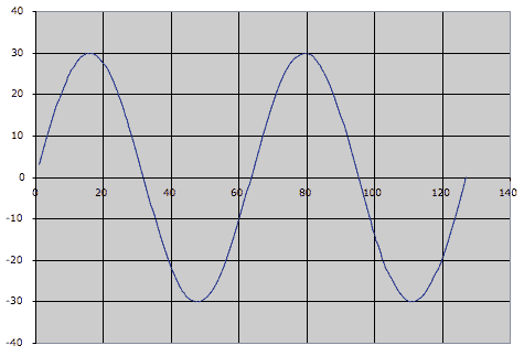
It’s a nearly perfect cycle of a sine wave. To chart out two full cycles, copy and paste E9 to I9:

One thing to keep in mind here is that the CV output limits change as you raise the Drive value. At a 1/4 sine wave setting (Drive value at 0 and a scale value of 34 with Rotary 2 at 0), the Shaper will output a CV value of +50 (it’s not entering the negative range of the bipolar output). At the 4 sine wave settings (Drive value at 91 and a scale value of 2 with Rotary 2 at 4) the Shaper will output a CV vale of +/- 29. The spreadsheet changes all of this for you, and adjusts the chart accordingly.
Viewing the CV value in Thor
- To view the CV value in Thor, let’s first make sure we’re seeing true +/-127 values from the Mod Wheel, so place this Thor inside a Combinator, and in Thor’s Modulation Bus Routing Section, make the following assignment:
Source -> Amount -> Destination -> Amount -> Scale
Mod Wheel -> 100 -> CV Out 1
- Now route CV 1 output on the back of Thor to the Combinator’s Rotary 1 input. In the Combinator’s Modulation Routing Section, make the following assignments:
Source -> Target -> Min -> Max
Rotary 1 -> Mod 12 Destination Amount -> -100 -> +100
Rotary 1 -> Mod 13 Destination Amount -> -27 -> +27
- Change Combinator knob 1 from 63 to 64. This visualization isn’t perfect, but it’s fairly close. Raise the mod wheel and note the two amount values in Thor’s Modulation Bus Routing Section rising with the mod wheel. At full throw, they should add up to 127, and at 0 it’s approximately 0 (you may see negative values). Now modify the previous assignment to this:
Source -> Amount -> Destination -> Amount -> Scale
Shaper -> 100 -> CV Out 1
- Raise the Mod Wheel and you’ll find the values range from approximately +34 down to -36. This is basically a range of 70, so we can essentially call this +/- 35.
So… what is all this good for? What are the applications? I don’t know yet, but it does potentially open up a lot of possibilities for those folks out there with creative and curious minds. One design is a 4 source cross-fader, which is included in the Project files (download above). The Combinator is within a Reason file for maximum compatibility with everyone out there.
Inside this Combinator you’ll notice that the Shaper Driver values for “CV2” and “CV3” Thor units are set for 42, which to my ears extended the fade out time for the mixer faders to a better sounding value. The “CV2” and “CV3” Thor units are identical, except via the Combinator Modulation Routing section, CV3 Thor’s Mod Wheel values are inverted, so the full throw is 0, and the lowest position is 127. This is essentially allowing you to send that sine wave backwards (not upside down) via the Combinator knob. I know, that’s confusing a bit, but sit and stare at your screen for a few hours and it might make sense – it took a while to figure it out, and now it makes sense to me, but it wasn’t easy at first. These Thor units send bipolar CV data to raise and lower the mixer volume levels. When the values go into the negative, those CV values are of no use to the mixer, thus the channels remain at 0 volume. The other Thor, “CV1 and CV4” is sending out linear CV values as opposed to sine wave shaped values – these are being offset via a DC offset value from the two Step Sequencer CV values, one for each CV output. To add a bit of crossfade between 1&2 and between 3&4, adjust Rotary 1 on the “CV1 and CV4” Thor.
Well, that’s about it – hope this is mind-bending for you all.
Ed “EditEd4TV” Bauman
• NOW AVAILABLE ‘Reasonable Help 2010: http://baumanproductions.com/reasonablehelp.html
• Facebook: http://www.facebook.com/pages/EditEd4TV/46599212364
• Reason Files: http://www.baumanproductions.com/reason.html
• Tunes: http://www.soundclick.com/EditEd4TV
