79 – Introducing Pulsar

With the introduction of Rack Extensions from Propellerhead, we see a major shift of the company into the Plugin arena, although Rack Extensions are expressed as “plugins done right.” And the Props have introduced 3 new Re devices (Radical Piano, Polar, and Pulsar). Not too bad for a point release. Instead of focusing on the 6.5 release itself, and debating the cost (it’s been done to death in the forums), I thought I would start by taking a tour of Pulsar, a device that is free for 3 months, and $49 thereafter. Hopefully, by the end of this article, you’ll see why the price is justified. Pulsar is simple, fun, and capable of some very unique sound ideas. Let’s take a look at why this is the case.

With the introduction of Rack Extensions from Propellerhead, we see a major shift of the company into the Plugin arena, although Rack Extensions are expressed as “plugins done right.” And the Props have introduced 3 new Re devices (Radical Piano, Polar, and Pulsar). Not too bad for a point release. Instead of focusing on the 6.5 release itself, and debating the cost (it’s been done to death in the forums), I thought I would start by taking a tour of Pulsar, a device that is free for 3 months, and $49 thereafter. Hopefully, by the end of this article, you’ll see why the price is justified. Pulsar is simple, fun, and capable of some very unique sound ideas. Let’s take a look at why this is the case.

You can download the project files here: pulsar-synths. This zip file contains some Combinators and .reason files which go through some of the concepts I’ll discuss below.

Starting off with a simple LFO

At it’s most basic, Pulsar is a Dual LFO. But when you first add a Pulsar to your project, you’ll only be using LFO 1. In many cases, this may be all you need. And if that’s the case, you may be wondering why you would need yet another LFO in the Reason arsenal? Doesn’t Thor, Subtractor, Malstrom, and even some other devices have one or two LFOs that can be used (and have been used) by many since the birth of Reason? Sure. But Pulsar delivers something the other LFOs do not (apart from Pulveriser). It comes with a “Lag” feature. Furthermore, it comes with two other unique features: “Phase” and “Shuffle.”

To recap, the “Lag” feature is an LFO filter which smooths out the shape of the LFO. If you are using an LFO with a sharp edge (Square or Stepped, for example), increasing the Lag feature curves those sharp edges, and can reduce a lot of the abrupt “clicking” that can result from these LFOs.

“Phase” is used to shift the LFO forward or backward, kind of like a pulse width modulation for your LFO. Look at Thor’s Analogue oscillator set to a square wave. The Mod parameter works the same way by shifting the LFO forward or backward (widening or narrowing the LFO). When using two similar LFOs in Pulsar and adjusting their Phases (or automating Phase movement in real-time), you can create some really interesting modulations with the LFOs.

Finally, there’s a parameter we’ve seen time and time again, though not in an LFO: “Shuffle.” This parameter shuffles the LFO, making the movement or LFO automation more erratic. Keep in mind though, that while “Shuffle” provides some randomness to your LFO cycles, the cycles themselves will always be in sync. In other words, the start and stop of the waveform will be random, but their duration will always equal the time cycle that you set up in the timing of the LFO. And it’s important to note that “Shuffle” works in 2-cycle pairs. So looking at a 2-cycle waveform set to 1/4 Tempo Sync means that you have two cycles of the wave that equal 1/4 each. Cycle 1 will always start at the beginning of the cycle, but can end anywhere within both cycles. Then cycle 2 starts and always ends at the end of both cycles. Kind of an interesting strategy if you ask me. But putting the theory aside for a moment, the best way to get a feel for it is to try it out for yourself.

All three of these parameters are fairly unique to Pulsar. And so it might be worth your while to try using this LFO on it’s own the next time your modulation calls for it in your track.

There’s also lots of other interesting things you can do with Pulsar: Sync LFO 2 with LFO 1, Have the Level of LFO 2 affect LFO 1 (AM), have the Rate of LFO 2 affect LFO 1 (FM), trigger the envelope via LFO 2, and this doesn’t begin to get into the CV / Audio modulations on the back of the device. Using all of these features allows you to set up some very complex modulations and even use Pulsar’s LFOs as Oscillators to create some very unique sounding (somewhat Analog-style) synth instruments. We’ll dig into that further below.

But before going further, you should definitely check out the introductory video from the Props on how Pulsar can be used as an LFO and how those LFOs can be used as Oscillators. This is perfect for getting your feet wet with the device. And the final song result at the end of this tutorial is truly inspiring. So before doing anything more, let’s take a first look at Pulsar:

Accessing the Pulsar Patches

Pulsar can’t load or save patches. However, you can contain a Pulsar (along with any other devices to which Pulsar is connected) inside a Combinator and then save the Combinator. And this is a great time to bring up the fact that Pulsar comes with a wide variety of effects and instruments that were put together by some very talented patch designers. Here’s how you can access them:

  1. Right-click on the Rack and select “Create Instrument” or “Create Effect,” depending which option you want.
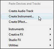
    Right-clicking on the rack and selecting "Create Instrument" or "Create Effect"
    Right-clicking on the rack and selecting “Create Instrument” or “Create Effect”
  2. The Reason Browser opens. Notice the “Rack Extensions” option under the “Locations and Favorites” area on the left side of the window? Click it, and you’ll see all your loaded Rack Extensions displayed on the right side.
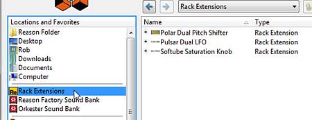
    The new "Rack Extensions" stock patch bank in Reason 6.5
    The new “Rack Extensions” stock patch bank in Reason 6.5
  3. From this list, select Pulsar directly by double-clicking it and navigating down the folders to all the available patches. Alternately, you can click the plus (+) sign and drill down to the patch you like.
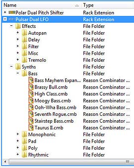
    The Pulsar stock patch bank expanded
    The Pulsar stock patch bank expanded on the right side of the Browser window.
  4. Double-click on the patch of your choice to open it in the Rack.

    The Pulsar patch loaded into the Rack (with a great new Combinator backdrop by the way).
    The Pulsar patch loaded into the Rack (with a great new Combinator backdrop by the way – nice job Propellerheads!).

Of course, if you’re saving your own patches, you’ll have to save them to your own computer location. All Pulsar patches need to be saved as a Combinator device. So all the patches you’ll find underneath the Pulsar stock patches are Combinators.

I strongly urge you to have a look at these patches. They showcase how you can use Pulsar in all manner of ways. There’s a way to use it as a dual gate, dual wah, LFO filter wobbler, FM, AM, etc. So opening the patches to get a feel for Pulsar is a great way to learn how to use it.

Pulsar as Dual Oscillators: Cheap on CPU, not Cheap on Sound.

And now for the major coup. Yes, you can use Pulsar as a dual Oscillator to create all manner of synth sounds. Trust me, I’ve tried. For those using Reason essentials, this provides a great alternative to the Subtractor synth. You now have a second synth inside Reason. And for those using Reason, you’ll be thrilled to know you not only have a simple synth, but process this synth through Thor, and you have a very amazing sound generation tool that is quite unlike the other sounds in Reason (whether that sound is good or bad is something I’ll leave for you to decide, as it’s a raw aliased sound that some like and some don’t). But nevertheless, it’s a unique sound with which you should experiment.

First, the video:

Let’s start off slow and figure out how to use Pulsar as a synth on its own. Since Reason Essentials doesn’t come with Thor, this is really the only way to go for that group of users. And yes, you can most definitely use Pulsar as a synth on its own. This is really great for Bass sounds, and in my opinion, this is where it shines. So let’s get started with a very simple setup:

  1. Right-click on the rack and select Utilities > Combinator. Inside the Combinator, right-click and select Utilities > Pulsar Dual LFO.
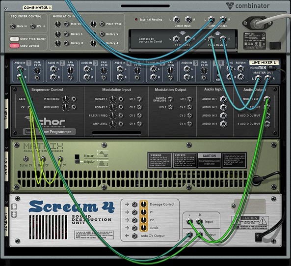
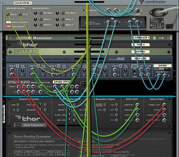
  2. Flip to the back of the rack and send LFO 1 Audio Output 1 from Pulsar to the Left “From Devices” Combinator Audio input. Then send LFO 2 Audio Output 1 from Pulsar to the Right “From Devices” Combinator Audio input. This way, LFO 1 produces the sound for the Left side of the stereo field, and LFO 2 produces the sound for the Right side of the stereo field.
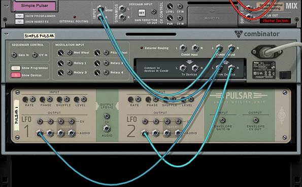
    The Routings from the Pulsar to the Combinator
    The Routings from the Pulsar to the Combinator
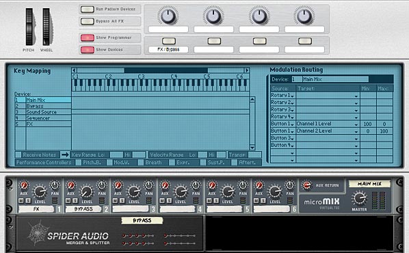
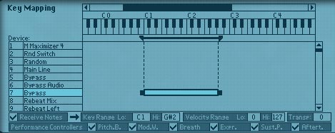
  3. Open the Combinator’s programmer and select the Pulsar device. At the bottom left side of the screen place a checkmark in the “Receive Notes” checkbox. This allows you to play the Pulsar through the Combinator’s MIDI note input.
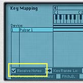
    Selecting the Pulsar device in the Combinator's Programmer and ensuring it "Receives Notes"
    Selecting the Pulsar device in the Combinator’s Programmer and ensuring it “Receives Notes”
  4. It’s important in this kind of setup to ensure that the parameters for both LFOs are set exactly the same, otherwise you’ll hear differences in the sound coming from both the left and right sides of the stereo field. Start by turning Off the Tempo Sync for LFO 1, and turn On LFO 2 (On/Off button). Switch LFO 1 and LFO 2 Waveforms to Sawtooth waves. Then reduce the “Level” rotaries to 0% for both LFOs. Increase the Shuffle knobs to 70% for both LFOs.
  5. In the Pulsar Envelope section at the right side of the device, reduce the Release amount to zero (0) ms. Increase the Envelope Rate for both LFOs to 100%, and increase the Envelope Level to about 60% for both LFOs.
  6. If you play the Combinator through your MIDI keyboard at this point, there is no key scaling. No matter what key you play, you’ll hear the same note pitch. In order to scale the keyboard, you must turn the MIDI KBD Follow knob on Pulsar fully right to 100%. Once you do that, you’ll have yourself a nice little patch that should play a pretty cool bassline in the C-1 to C2 range.
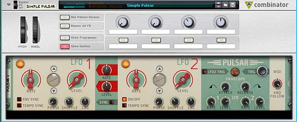
    The Pulsar's front panel setup
    The Pulsar’s front panel setup

Advanced Pulsar Synth Processing through Thor

Let’s take it up a notch:

There’s two ways you can process Pulsar through Thor: Both methods involve sending the audio outputs from LFO 1 and LFO 2 into Thor and then entering the following two lines into Thor’s Modulation Bus Routing Section (MBRS):

Audio In1 : 100 > Filt1 In

Audio In2 : 100 > Filt1 In

As long as both the Pulsar and Thor are receiving notes, and are inside a Combinator, you’re all set. Ensure that both LFO 1 and 2 on Pulsar are not Tempo Synced, and turn the rates all the way up (fully to the right). Also keep the Pulsar Envelope settings at their default, and turn the MIDI KBD Follow knob all the way right to 100%.

The cool thing about this setup is that you can use Thor’s Portamento, Shaper, Filter 1, Filter 2, Amp Envelope, Amp section, and pretty much everything else in Thor to shape the sound of the Pulsar LFOs. In this instance, you’re simply replacing Thor’s Oscillators with Pulsar’s LFOs (which are used as Oscillators).

One thing to keep in mind with this approach is that since you’re processing the audio through the Amp section, the levels of your audio are going to be adjusted using both the Thor Amp Gain and Pulsar’s LFO Level controls. So watch those levels!

The second approach builds on the first and bypasses most of Thor by sending the audio into Filter 3. So after you’ve entered the two audio lines in the MBRS as above, enter the following two lines in the bottom right two MBRS entries as follows:

Filter 1 : 100 > Filt3 L.In : 100 > Amp Env : 100 > MIDI Vel

Filter 1 : 100 > Filt3 R.In : 100 > Amp Env : 100 > MIDI Vel

With this approach, you’re bypassing everything between Filter 1 and Filter 3. This means no Shaper, no Filter 1 and 2, and normally, no Amp Envelope either. However, since you’re scaling the audio using the Amp Envelope explicitly in the MBRS, then you can still use the Amp Envelope to adjust your audio. The advantage is that you gain a 4-stage envelope (Attack, Decay, Sustain, and Release) with Thor, instead of a 2-stage envelope with Pulsar (Attack and Release). Also, you can use the Delay and Chorus FX in Thor to affect the synth sound.

One note though. You can’t use Thor’s Amp section for any adjustments. So all the volume control resides in Pulsar’s LFO 1 and 2. And it suddenly occurs to me that all of this is in the video, so check it out if any of this sounds esoteric to you. Have fun!

Oh and in case you missed it, here’s James Bernard’s take on Pulsar. Pretty awesome sampling technique. Don’t miss this one either:

http://www.musicradar.com/tuition/tech/video-how-to-use-propellerhead-pulsar-as-a-playable-synth-549579

The downside is that you need Reason to do these wonderful Thor processing tricks. No can do with Reason Essentials. So upgrade already!


So that’s how you set up Pulsar as a synth. Try out the different waveforms and have a blast making some new sounds. And if you have any other Pulsar tricks, be sure to let us all know. Cheers!

78 – Creating Better Patches (Part 5)

In this fifth installment of my series on better patch design, I thought I would take a much-needed break from all the theory and synth jargon, and instead focus on some creative Thor synth ideas. I can almost hear the collective yawn after reading the last few articles. So let’s spice it up with a few videos that showcase some of the concepts we’ve talked about, but more importantly, let’s just have some fun fiddling around in Thor.

In this fifth installment of my series on better patch design, I thought I would take a much-needed break from all the theory and synth jargon, and instead focus on some creative Thor synth ideas. I can almost hear the collective yawn after reading the last few articles. So let’s spice it up with a few videos that showcase some of the concepts we’ve talked about, but more importantly, let’s just have some fun fiddling around in Thor.

You can download the project files here: better-patches-part5. This zip consists of a few Thor patches and demo .reason files that outline the ideas below. You can use any version of Reason above 4.0 (when the Thor synth was introduced to the world of Reason). Enjoy! Read on for more about these ideas.

The Hoover Sound (Redux)

Chris Petti did a great video on how to create a Hoover Sound in Reason using some Analog Oscillators and a Multi-Oscillator to fatten everything up. If you haven’t seen his video, I’m going to showcase it here. Have a look and build the patch first. We’ll use this as the base building block and figure out a few modifications you can add to enhance it’s flexibility. Here’s his video:

This patch is a really great sound as it is, and Mr. Petti does a bang up job of presenting it to us (not to mention his videos are way cooler than my own DIY camera work). Nonetheless, there’s lots you can do to add to his patch. So I’m going to start where Chris left off and see what we can do to make his patch more flexible, taking it to the next level of patch design. Check out the video below:

Button Trigger Madness

In my never-ending quest to solve interesting problems in Reason, I came across this dilemma. How can I use the button in Thor as a toggle switch to step through the Thor Sequencer? I wasn’t happy with the “it’s not possible” answer. So here’s what I devised. It’s actually a nice simple solution which allows you to use the Thor button as a cycler. The power in this trick is that when the Sequencer is set to “Step” mode, the button can be used to cycle through all 16 steps. If you watch the video below, you’ll see how this can help you devise Thor patches that contain 16 distinct sounds within a single Thor patch.

Here’s the short version of how you set it up (see the Chiptune video below for a practical application):

  1. Open a new Reason document. Go into Edit > Preferences, and on the “Audio Tab,” ensure the Sample Rate is set to 44,100 (should be the default). Then close out of this dialog.
  2. Create an initialized Thor device.
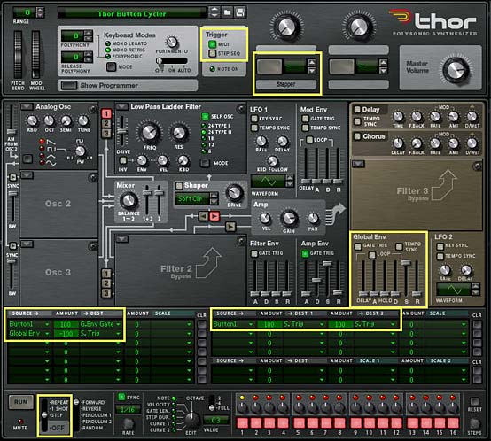
  3. Turn off the “Step Sequencer” green light in the Global section’s “Trigger” area. While we’re doing that, label Button 1 the “Stepper.”
  4. Turn off the Global Envelope’s “Gate Trig” green light.
  5. Turn up the Global Envelope’s Sustain to full (0.0 dB), and turn down all other Global Envelope parameters to zero.
  6. In the Modulation Bus Routing Section (MBRS), create the following two lines on the left side:

    Button1 : 100 > G.Env Gate

    Global Env : -100 > S. Trig

  7. Now, enter the following in the MBRS on the first line on the right side

    Button1 : 100 > S. Trig : 100 > S. Trig

  8. In the Step Sequencer section, change the Run Mode to “Step.”
The Thor Button Cycler, showing all the changes that need to be made to the Thor init patch

Now when you press button 1, you’ll notice that the Step sequencer moves forward one step when turned on, and another step when turned off. In essence, we’ve tricked Thor into thinking that both button “on” and button “off” should trigger the Step Sequencer to “Run.” The Global Envelope was required because it is always left on, and so can be manipulated without requiring a Midi Note to “gate” the envelope.

You can now use the Step Sequencer’s Note, Curve 1, Curve 2, Gate Length, etc. to control any aspect of the Thor patch that you like, and build up different sounds at each step of the Step Sequencer. Think of generating 16 different Bass tones or 16 different Pads, Strings, Drum sounds, or any interesting sounds you can dream up. The only limitation is that you won’t have access to the Global Envelope — a minor limitation given the fact that you can get Thor to generate 16 different sounds from a single patch.

Chiptune Sounds (Redux)

As I was experimenting one day, I stumbled upon. . .

. . . a wonderful way to create some Chiptune sounds using the Wavetable Oscillator in Thor and affect it’s “Frequency (FM)” parameter with a stepped LFO. Sometimes it’s not how crazy you can make things. Instead, it’s about keeping things ultra simple. Have a look at the video to see how I paired this Chiptune idea with the above “Button Trigger Madness” idea to create 4 different Chiptune sounds within a single Thor patch.

Here’s the video:

Creating a Sweep

This is an interesting patch that will show you an alternate use for the Velocity performance of the Patch. Since the sweep changes the Volume (along with a few other parameters) over time to sweep the sound upward to full volume, you probably don’t want to have Volume modulated by Velocity. Instead, you can use the Velocity information from the musician’s performance to adjust the speed or rate of the sweep, making it rise slowly when the keys are played softly, and faster when the keys are played harder. You could also set up a button to reverse the Velocity behavior, if you like (see my previous tutorials in this series for explanations on how this is done).

Here’s the video:

Using the FSB for Practice

Another idea I had was to take patches from one synth and transfer them over to another synth within Reason. In this video, I’ll show you how you can take one of my favorite Subtractor patches and recreate the sounds inside Thor. While not every sound from the Subtractor (or Malstrom, for that matter) can be accurately reflected in Thor — they are, for the most part, different synthesis algorithms and techniques underlying each synth — you can still get pretty close, depending on the patch you start out with. It’s good mental exercise. It will help you get to know all the synth parameters and how they work. And you have an endless array of sounds at your fingertips in the FSB.

So why not give this a try with your favorite sounds? And there’s also another reason to transfer patches from the Subtractor into Thor: At the end of the transfer, you’ll still have the Rotaries, Buttons, and step sequencer to enhance or expand on the patches — something the Subtractor lacks. So here’s the video to show you the method I used:


So that’s part five in the series. As always if you have any questions or want to contribute your thoughts and ideas, I encourage you to do so. I’m always interested in hearing new ways you’ve found to work with Reason. All my best until next time.

77 – Creating Better Patches (Part 4)

In this next installment of the Reason 101 guide to creating better patches, I’m going to focus on setting up the Wheels, Rotaries, and Buttons in Thor, and discuss some creative ways you can implement your modulations. Hopefully this will provide you with some further inspiration when you’re building your sounds.

In this next installment of the Reason 101 guide to creating better patches, I’m going to focus on setting up the Wheels, Rotaries, and Buttons in Thor, and discuss some creative ways you can implement your modulations. Hopefully this will provide you with some further inspiration when you’re building your sounds.

The Pitch Bend & Mod Wheels, and four assignable controls (two Rotaries & two Buttons) in Thor's Controller Panel

The Pitch Bend Wheel

The Pitch Bend Wheel is a bipolar (it goes both positive and negative) bend wheel that is normally used to apply pitch modulation to the sound. The bend modulates the pitch smoothly upward or downward by a specific set of semitones (as outlined in the “Range” field — Thor can go from 0-24 semitones for a maximum two octave range). In terms of MIDI data, the Pitch Wheel goes from a value of -8,192 to 8,191. In the majority of circumstances, you’ll want the Pitch Wheel to modulate the note value (pitch) of the sound, and this is the default behavior (meaning, you don’t need to set anything up in the MBRS to use it to control the Pitch of your patch – however, you DO need to have the KBD knob in the Oscillators tracking the keyboard for the Pitch Wheel to have an effect on pitch – the knob should be set at a position other than zero, and usually set fully right). However, there are cases where pitch is either not necessary to the sound you are developing, or you may simply wish to modulate something other than pitch. You can easily do this in Thor.

A good example where Pitch may not be necessary is if you are using the Step Sequencer to set up a specific sequence to play the Thor patch with specific note values in mind, or if you are restricting your patch to play at specific pitches, and don’t want the user changing the pitch on you. If that’s the case, you set up the sequence using the Note value in the step sequencer. Another example might be if you have a drum sound that doesn’t require pitching. Though, I have to admit, it’s pretty rare that I program something other than Pitch on the Pitch Wheel.

If you are NOT going to use the Pitch Wheel to modulate the Pitch parameter in Thor, you’ll need to do the following:

  1. First, if your patch is pitch-capable, meaning you are tracking pitch along the keyboard (using the KBD knob set fully right in the oscillator sections), you can force the Pitch Wheel to be non-responsive to the pitch by reducing the Pitch Wheel range to zero (0).
  2. Next, I would strongly advise you to assign something to the Pitch Wheel using the MBRS. Remember that most everyone that has a Piano, Organ, or MIDI controller will have a Pitch Wheel, and to leave it unassigned is going to make the musician wonder why nothing is happening when they use it. And this article is all about making better patches right? So assign something to the Pitch Wheel.
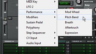
The Pitch Bend and Mod Wheel options in the MBRS under the "Performance" submenu. They can be used as Modulation Sources or Scales.

When you assign a parameter to the Pitch Wheel, remember that the wheel is bipolar. This makes it a little more tricky when assigning modulation parameters. If the destination you are modulating is already bipolar in nature, it’s relatively straightforward. The most obvious parameter I can think of is the Amp > Pan parameter. By default, the Amp Pan knob in Thor’s voice section is centered in the middle of the stereo field. If you add the following line in the MBRS:

Pitch Bend : -100 > Amp Pan

Then, when the Pitch Wheel is pushed upward, the sound is panned left. When the Pitch Wheel is pushed downward, the sound is panned right. As with all MBRS settings, you can reverse this relationship, as follows:

Pitch Bend : 100 > Amp Pan

Then, when the Pitch Wheel is pushed upward, the sound is panned right. When the Pitch Wheel is pushed downward, the sound is panned left.

The default position of the Pitch Wheel is the same as the position of your Amp Pan knob (centered in the stereo field). If you were to change the position of the Pan knob to be more left or right, the Pitch Wheel will have a different “starting” position, based on this pan knob’s position.

So now, if you want to use the Pitch Wheel as a source to modulate a unipolar destination (Amp Gain, for example), you need to think a little harder about your starting position for the gain knob. If you turn the amp gain knob all the way down (fully left), and enter the following in the MBRS:

Pitch Bend : 75 > Amp Gain

The Pitch Wheel will turn the Gain up by 75% in volume when you push the wheel upward. But nothing will happen when you push the wheel downward. In order to have some movement in both directions, you need to turn your unipolar destination control (the Amp Gain knob in this example) to a more “middle” starting location. This is because the Pitch Wheel is bipolar and can move in two different directions (up or down). The Amount in the MBRS which is assigned between the Pitch Wheel and the destination determines how much the destination is modulated “in both directions.” Positive or Negative amount values simply determine which direction the modulation occurs. Put another way:

Positive Mod Amount = Pitch Wheel up (moves Positive from the destination’s start position); Pitch Wheel down (moves Negative from the destination’s start position).

Negative Mod Amount = Pitch Wheel up (moves Negative from the destination’s start position); Pitch Wheel down (moves Positive from the destination’s start position).

Of course, there’s nothing stopping you from combining effects. You could raise the Pitch Wheel range back up to 2 (whole tone; major second), 4 (major third), 7 (perfect fifth) or 12 (Octave), and combine the Pitch bend with the Pan bend. Or any other combination of Thor destination parameters you like.

In the physical world, the Pitch Wheel’s default starting position is in the middle (in the virtual world, this is a bipolar value of zero), and you can move the Pitch Wheel up (positive) or down (negative). If you move the wheel all the way up or down, and let go of the wheel, an internal spring will send it back to the zero position. In Reason, the same thing happens. If you move the Pitch Wheel up with the mouse, for example, and let it go, the wheel reverts back to the default zero position. For this reason, you cannot save the Pitch Wheel in a position other than zero when saving your patch.

Of course, if you are saving the song file, there is a very simple workaround for saving the Pitch Bend at a location other than the default zero. Simply add an automation lane in the main sequencer in your song, and draw the automation at any value you like. Then save the song. The automation forces the Pitch Wheel to be saved at a location other than zero. This is probably never necessary though, if in fact you are using the Pitch Wheel to control Note Pitch, because you can always just change the pitch of your Oscillators in Thor. But this could be a valid approach if you have some other modulations set up on the Pitch Wheel and need to have the Wheel start at a value other than zero.

The Modulation Wheel

The Mod Wheel is a unipolar (it goes positive only) wheel that is used mainly for Vibrato, Tremolo, or both. From a MIDI standpoint, it goes from a value of zero (0) to 127. However, as with the Pitch Wheel, the Mod Wheel can be used to modulate any parameters you like in Thor. By default, the Mod Wheel always starts from a position of zero as well, but it does not “spring” back to zero if you raise it and let go of it. For example, if you move the mod wheel up to a value of 70, then save the patch. The next time you open the patch, the Mod Wheel will “start” at zero. But if you are performing while using the Mod Wheel, you can raise it to 70 and let go. It will still remain at 70 until you stop the song. The value setting of 70 is not retained from session to session, but is retained while you are performing. In the world of physical controllers, the Mod Wheel has no spring.

Of course, there’s nothing preventing you from drawing an automation lane for the Mod Wheel in the main sequencer in Reason, and assigning a different value, then saving the Reason song file (as explained in the Pitch Wheel note above).

Since the Mod wheel is common to about 99% of all keyboards, both traditional piano instruments and MIDI Keyboard controllers, and Rotaries / Buttons are much less common, I usually ensure that the modulation that is most important for the patch is applied to the Mod Wheel. Less important modulations should be placed on the Rotaries and Buttons. Aside from that, if your patch calls for Tremolo or Vibrato, the Mod Wheel is a good location for this, since it just “makes sense” for the musician to access these effects from the Mod Wheel.

It should also be noted that while the focus of this article series is using the front panel of Thor to modulate parameters and build better patches, you have several CV options on the back of Thor. These CV options can be used to control the Pitch and Mod Wheels, Rotaries, and Buttons of Thor (Note: Buttons have no direct CV inputs or outputs, but can be controlled by wrapping the Thor inside a Combinator and using the Combinator’s programmer).

User-Assignable Rotaries

The two Rotaries in Thor’s Controller panel can be used to modulate any parameters in Thor via the MBRS. Practically speaking, the Rotaries serve the same purpose as the Mod Wheel, except that it’s a knob instead of a wheel. There’s also one other difference: Rotaries can have a starting position anywhere between the left and right side of the dial. Something the Mod Wheel cannot do (the Mod Wheel always starts at a position of zero, remember). I typically use Rotaries to create variations in the Timbre of the patch, frequency, FM applications between Oscillators and filters, Mixing between Oscillators, Crossover effects (see my Thor Crossfading Techniques for some ideas on this),  Delay or Chorus levels, or any other aspects of the patch that could prove useful.

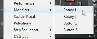
The two Rotaries and Buttons in the MBRS under the "Modifiers" submenu. They can be used as Modulation Sources or Scales.

If the patch is a drum patch, I sometimes will put the delay time on the Rotary and then have the Delay On / Off assigned to a button under that Rotary. This can produce rolls for your drums. Of course, these are all just idea springboards. You can assign any source parameter to modulate any destination parameter in Thor, and so outlining them all is not practical in a tutorial such as this. The key here is your imagination and creativity.

One piece of advice though: If you are assigning modulations to the Rotary (as a source), try to assign more than one destination in Thor. For example, assigning Rotary 1 to control the Filter Frequency will at least make your patch “good” because you at least have Rotary 1 doing something. But assigning Rotary 1 to raise Filter 1 Frequency while reducing Filter 1 Resonance, or assigning Rotary 1 to Raise Filter 1 Frequency while reducing Filter 2 Frequency and at the same time raising the AM amount between two oscillators can raise your sound design idea from “good” to “great.” I’m not saying that every Rotary and Button should have more than one assignment, but often times, you can create more subtle variation in the sound, or create something that is much more dynamic, responsive, and unique by layering your modulations. This advice goes not just for the Rotaries, but any modulations you develop inside your patch. Always look at ways you can improve upon what you’ve done. And always try lots of experimentation. Sometimes you’ll come across an unexpected result that can improve your patch.

User-Assignable Buttons

The two Buttons in Thor’s Controller panel can be used to modulate any parameters in Thor via the MBRS. Because the buttons can contain only two positions, this makes them the perfect place to create on/off modulations. However, it would be careless to think that these controls are simplistic. You can create some amazing variety within a two-setting limit. For example, think about creating two distinct instruments within a single Thor patch. Or even four, if you want to be so bold and use two different buttons. These are what I call “Hybrid” patches. Here is one example:

First, you can easily change a Synth sound into a Pad sound using little more than the Attack and Release of the Amp Envelope. Leave the Decay and Sustain levels somewhere in the middle or higher up, and when the Attack and Release are short, the patch can sound like a synth. Modulate the Attack and Release higher up, and the synth will take on a pad-like quality. In the MBRS, the settings would go something like this:

Button1 : 75 > Amp Envelope Attack | 75 > Amp Envelope Release

Note that you can set up two destinations in the top right MBRS row, which sets up a shorthand to use one source to modulate two different parameters. This uses one single row for two modulations.

Try creating a Bass / Synth hybrid or a Bass Drum / Snare Drum hybrid. Challenge yourself to come up with a few hybrid patches like this, just for the fun of it.

Some other modulations I usually place on the buttons are things like a one-stop Chorus or Delay on/off button. For example, if I’m putting the Chorus on a button, I first turn on the Chorus, then set up the Chorus parameters to specific settings that works with the patch I’m creating (Delay, Feedback, Rate, and Amount; but not the Dry/Wet knob). Once I have everything set up, turn the Dry/Wet knob completely off (turned fully left). Then in the MBRS, I would add the following line:

Button1 : [“X” Amount] > Chorus Dry/Wet

where “X Amount” is the amount you set up as you listen to the patch and play it back. Usually settings between 60-80 are a pretty good range, though it depends on the sound you’re going for.

Since you have turned off the Dry/Wet knob in the Chorus section, the Dry/Wet value is determined entirely with the MBRS setting you just entered. When the button is off, there is no Chorus. When the button is turned on, the Chorus you just set up is turned on. Simple and elegant.

Think about putting a Drum Roll on the button using Delay, or using the Shaper or FM between oscillators to create distortion. Or Frequency Wobbling for a bass. As with the Rotaries, the sky is the limit. Modulate, modulate, modulate.

Lastly, another reason I use Buttons is to reverse modulations around. I alluded to this when I was discussing Velocity in Part 2 of this series, but let’s look at it from another example. Let’s say you modulate your pitch upward using the Mod Envelope. You would first raise the Decay of the Mod Envelope, and then set up two lines in the MBRS as follows:

Mod Envelope : 30 > Osc1 Pitch : -100 > Button 1

Mod Envelope : -30 > Osc1 Pitch: 100 > Button 1

This means that when the button is off, the Decay of the Mod Envelope bends the pitch upward by an amount of “30” (noted by the first line in the MBRS). When the button is turned on, the same Decay of the Mod Envelope bends the pitch downward by an amount of “30” (noted by the second line in the MBRS). The button acts as a reversal of your modulation.

Button Key Triggers

One other really useful aspect of the buttons is the fact that you can assign a MIDI Key from your keyboard to turn the Button on and off. Use the arrows to the right of the Button (also called a “spin box” control) to select a key. Then as you play, use the Key that is assigned to that button to turn the button on. This works as a “Momentary Trigger,” meaning that the button will remain on as long as your key is pressed down on your keyboard, and turns off when you lift your finger off the key.

For example, if you set up the Chorus on a button as I outlined above. Then use C-2 as the key trigger, you can play your patch using any of the other keys, and press C-2 to hear the Chorus affecting the sound of your patch as you play. If you have set up the hybrid Synth/Pad patch that I outlined above, you could easily switch between the two timbres of the patch using a key trigger, and do all of this “Live” as you play. Great fun

Thor’s Built-in Tutorials & Mod Wheel Vibrato

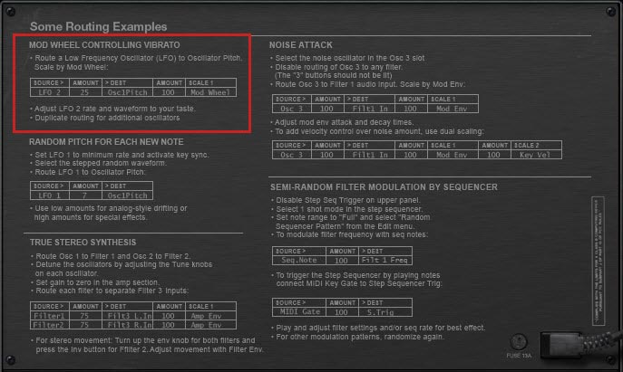
If you flip to the back of the Thor device Programmer panel, you’ll see a lot of great tutorials that can be used as starting points. Let’s take a look at the first one, which sets up Vibrato on the Mod Wheel, and see if we can expand on it. This will also be a good excercise to show you how changing a few MBRS settings can extend the power of one simple concept: Vibrato, turning it into a Vibrato / Tremolo crossfade that can be turned on and off.

Vibrato tutorial on the back of the Thor Programmer panel, among many other useful tutorial ideas.

First, Let’s flip back to the front panel again and Initialize the Thor patch.

Enter the Mod Wheel Vibrato settings in the first row of the MBRS, as outlined in the above Thor tutorial.

Next, let’s set up Tremolo (change in volume) on the Mod Wheel to hear how that sounds instead of Vibrato. Just change the destination from “Osc1Pitch” to “Amp Gain.” And turn the amount between the Source and Destination up to around 66, so we can hear the effect better. That’s pretty easy stuff right?

Ok. Let’s take things a little further by creating a cross-over between Tremolo & Vibrato and place it on Rotary 1 instead of the Mod Wheel, by replacing the line we entered previously with the following two lines in the MBRS:

LFO 2 : 25 > Osc1 Pitch : -100 > Rotary 1

LFO 2 : 66 > Amp Gain : 100 > Rotary 1

This is a great way to use one Rotary to control the Vibrato & Tremolo effect of your patch, however, it means that the effect is always applied to the sound in your patch. There’s no way to turn the Vibrato & Tremolo “off.” To do this in a very clean way inside the Thor MBRS, you can utilize the “double-scaler” rows located in the bottom right part of Thor’s MBRS. Be sure to delete the above lines in the MBRS and replace them with the two lines shown below. Also don’t forget to label the Rotary 1 and Button 1 as shown below:

Using Rotary 1 to Crossover between Vibrato and Tremolo, then setting up Button 1 to turn the Vibrato/Tremolo on or off.

This process of adding a second scale to both lines allows us to scale our modulations with two different controls. Put another way, the pitch and amp gain are always controlled by Rotary 1 from left to right when Button 1 is on, but they are not controlled by Rotary 1 when Button 1 is off. With a little extra thought, and a few more MBRS assignments, you can use Rotary 1 to control something completely different when Button 1 is off as well. This way, Button 1 becomes a switch between the Vibrato/Tremolo effect AND something else. It also means that Rotary 1 will be modulating something inside your patch, whether Button 1 is On or Off. But I’ll let you take it from there and figure that one out on your own. If you’ve been following all these tutorials, that should be child’s play for you.

More Great Sound Design Ideas

The Props are putting on a really great video-based series centered around Sound Design, and they’ve been kind enough to post my articles on their Facebook page in conjunction with this series. So I wanted to return the favor and provide a link to check out their videos here (in the event you’ve been living under a rock and haven’t heard about them). You’ll learn a lot from each one of them. Check them all out in the following playlist:


So far, we’ve gone through the discussion of keeping Consistent levels, working with Performance parameters such as Velocity, Key Scaling, Aftertouch, and Wheel assignments; and dealing with the User-assignable Rotaries and Buttons. Along the way, I hope I’ve also given you a thorough introduction to the Modulation Bus Routing Section (MBRS) in Thor. In the next part, I’ll go through a few more examples to take what we’ve learned here and translate it into some patch design ideas and improvements to existing patches. More thoughts on all this later. In the meantime, tell me what you think of this series, and let me know if you have any ideas that have come out of these articles. As always, I’d love to hear from you. Happy music-making!

76 – Creating Better Patches (Part 3)

In this third part of Reason 101’s guide to creating better patches, I’m going to continue to focus on Performance parameters in Thor. This time, I’m going to go over Key Scaling / Key Tracking, both in Thor’s Programmer panel, as well as in the Modulation Bus Routing Section (MBRS), as well as touch upon Aftertouch. Finally, I’ll go over a strategy you can use to approach setting up your Key Scaling parameters to get the most out of your patch and the keyboard’s range.

In this third part of Reason 101’s guide to creating better patches, I’m going to continue to focus on Performance parameters in Thor. This time, I’m going to go over Key Scaling / Key Tracking, both in Thor’s Programmer panel, as well as in the Modulation Bus Routing Section (MBRS), as well as touch upon Aftertouch. Finally, I’ll go over a strategy you can use to approach setting up your Key Scaling parameters to get the most out of your patch and the keyboard’s range.

Key Scaling / Key Tracking

Key Scaling or Key Tracking allows the designer to use pitch information to modulate any other synth parameter. If Velocity is the vertical aspect of playing a keyboard (how hard you press down on the keyboard), Key Scaling refers to the horizontal aspect of playing a keyboard. It refers to where you play the keyboard along the key register. Put simply, which notes are you playing? And what happens to the sound when you play different notes along that key scale (from -C2 to G8).

Many times when you build a patch, it will sound really great on a certain section of the keyboard (a specific range), but seldom does the sound work well across the whole keyboard range. If you go too low on the scale, sounds can become distorted or muddy, and if you play too high, they can become too bright or ear-piercing. To rectify this, you can employ some key scaling modulations to counteract these effects. For example, you can instruct Thor to lower the amplitude at one end or the other, or you can have Thor open up a filter at higher registers and close the filter more at lower registers. Or you can reverse this relationship if that works better for your sound. In much the same way that you can alter the Velocity of a patch in the MBRS, you can also alter the Key Scaling of almost any Thor parameter in the MBRS to create wild Key Scaling modulations, or very subtle variations in sound, based on the pitch information coming into Thor from your MIDI keyboard.

Typically, you would employ Key Scaling modulations for the following reasons:

  1. To extend the range of usefulness in your sound / patch to work farther up or down the keyboard scale.
  2. To restrict the usefulness of a patch to a specific range along the keyboard.
  3. To better mimic the way a traditional instrument sounds when played further up or down the keyboard scale. For example, both pianos and guitars become brighter at the high end and deeper at the bottom end. In addition, there is less sustain at the top end (faster), and more sustain at the bottom end (slower). You can use Key Scaling to mimic this behavior by applying the key scaling as a source to affect both filter frequency and amp envelope sustain as destinations.
  4. For some kind of special effect. For example, key tracking an LFO so that it is slow on the lower end of the scale and faster on the higher end. Or key tracking FM modulation between two oscillator, across the range of the keyboard.

Note: If you plan on restricting your sound to a specific range along the keyboard, I find it prudent to convey this to the user in the device’s patch name, so that the musician knows the location on the keyboard you intend them to play. For example, if your patch name is “Best Piano Ever,” rename the patch to “Best Piano Ever (C2-C4).” Otherwise, the musician might start playing the patch at C1 and wonder what Kool-Aid you were sipping when designing the patch. It’s not foolproof, but it’s a nice touch to improve the communication between designer and musician.

Fixed Key Tracking Parameters in Thor

So let’s take a look at the different ways you can use the fixed Key Tracking inside Thor. As with the fixed Velocity settings in Thor, you can turn Key Scaling parameters “on” or “off” (“enabled” or “disabled”). But before doing that, we need to know how all the fixed Key Tracking parameters work in Thor.

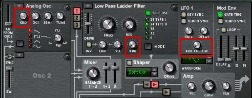
Fixed Key Scaling parameters in Thor's Programmer section

Oscillator KBD knob: Every Oscillator in Reason has the Oscillator KBD knob. This sets up how the pitch of the oscillator follows the keyboard scale. Put simply, when this knob is turned fully right, the pitch of the notes you play on the keyboard will play the pitch you expect. Higher KBD tracking = wider pitch range = more variation in pitch with each keyboard note played. However, if you turn the knob left, the pitch of the oscillator is reduced into a narrower pitch range. The Octave / Semitone / Tune knobs determine the base pitch of the oscillator (i.e.: determine how the keyboard scale is reduced). Think of this as your focal point for the base oscillator pitch. Lower KBD tracking = narrower pitch range = less variation in pitch with each keyboard note played.

Note: The Noise Oscillator is a special case. If set to the “Band” mode, Keyboard tracking has an effect on the Oscillator. All other modes cannot be tracked by the keyboard.

With the KBD knob set fully left, the base pitch of the oscillator is fully set by the Octave / Semitone / Tune knobs. In other words, no matter where you play the oscillator on your keyboard, the pitch of the oscillator will remain exactly the same. This can be useful if you are using your patch to create a drum sound perhaps, where you want the pitch of the drum to remain the same, no matter where the musician plays the sound on their keyboard.

When the value of the KBD knob is lowered (from right to left), the frequencies that are played on your keyboard are spread farther apart, resulting in pushing your Oscillator out of a traditional tuning. While there may be instances where this is the effect you are shooting for (an example would be if you use your Oscillator as a modulator for another Thor parameter, instead of a sound source), the majority of the time you’ll want this knob set either fully left or fully right.

Note: I’m not going to get into tuning your oscillators and discussing harmonics between oscillators in this tutorial. You could write books about it. But you might want to read up on the subject online. A few good resources are http://www.beatportal.com/feed/item/oscillators-mixing-and-blending/ and http://en.wikipedia.org/wiki/Harmonic_series_%28music%29

Filter KBD knob: All filters in Reason have the Filter KBD knob. This knob tracks the frequency of the filter across the entire range of the keyboard. It uses the pitch information from your MIDI keyboard to increase or decrease the filter frequency across the range of the keyboard. This works the same way as the oscillator KBD knob, except it’s the filter that is tracked along the keyboard. In plain english, the filter frequency is opened or closed depending on the the incoming pitch data from the MIDI keyboard.

In the case of the filter tracking, the Filter Frequency knob determines the base filter frequency. With the filter’s KBD knob turned fully right, the further up the keyboard you play, the more the filter is opened from this base frequency. The further down the keyboard you play, the more the filter frequency is closed from this base frequency.

If you turn the filter KBD knob fully left, there is no filter frequency keyboard tracking. Wherever you play the keyboard, the filter’s frequency will always remain static (based on the Filter Frequency knob). In other words, the pitch you play your keyboard does not change the filter frequency.

LFO 1 KBD Follow: As with the other KBD knobs, I’m sure you can now figure out how the LFO 1 KBD Follow works. You set the base LFO rate with the Rate knob, and then use the KBD Follow to track this rate along the keyboard. When set fully right, the higher up the keyboard you play, the faster the LFO rate becomes. The lower you play on the keyboard, the slower the rate becomes. This can be useful for all kinds of modulations.

Key Tracking and the MBRS

Now let’s turn to the MBRS and see how to apply Key Tracking there. As with the Velocity settings, Key Tracking in the MBRS works “in conjunction with” the fixed key tracking settings in the Thor panel. So you can use one or the other, or a combination of both, when creating your sounds.

The fixed Key Scaling parameters in Thor are good, but they are only a start. If you really want to get into interesting patch designs, you’ll need to break out into the MBRS. For example, the free-running LFO 2 does not have a KBD Follow knob, as its brother (LFO 1) does. So you will need to turn to the MBRS and put in a line that looks something like this:

KeyNote : 100 > LFO 2 Rate

This tells Thor to fully track the LFO 2 Rate along the entire length of the keyboard. Then you would use the Fixed LFO 2 Rate parameter knob to set the baseline LFO 2 Rate.

The following outlines the available Key Scaling options in the MBRS:

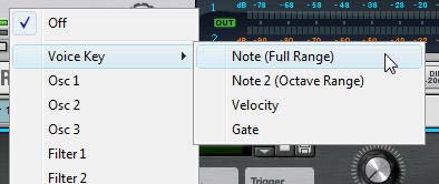
The Voice Key options in the MBRS Source submenu
The Voice Key options in the MBRS Source submenu (voice section).

Voice Key > Note (Full Range): This is the keyboard tracking in the voice (per note) section. It allows you to modulate any destination (or track, if you prefer) across the entire keyboard range. For example, let’s say we use it to track the pitch of the oscillator like so:

KeyNote : 100 > Osc1 Pitch

This is the same as if you were using the Oscillator KBD knob. However, remember that since both work in tandem, you will need to set the Oscillator KBD knob to zero (fully left) before adding this to the MBRS. Once you do so, you are now using the MBRS to set the pitch of the oscillator. Furthermore, there’s one other nice thing you can do in the MBRS that you can’t do with the KBD knob. Since the KBD knob is positive in value, you cannot set up a negative pitch. However, in the MBRS, change the amount setting to “-100” which reverses the pitch of the oscillator across the keyboard. Playing lower on the keyboard results in a higher pitch sound, while playing higher on the keyboard results in a lower sound. Very odd I know, and I can’t possibly think of why you would set it up this way or for what reason to be honest, but Thor allows you to do some pretty wild things. This being one of them.

Voice Key > Note 2 (Octave Range): This is exactly the same as the above “Note (Full Range)” setting, except for one very important point. If you use this setting, the key tracking spans a single octave, and will repeat itself each subsequent octave along the keyboard. So if, for example, you want to modulate the LFO 2 tracking using “Note 2 (Octave Range)” setting in a positive way, the LFO rate will go from slow to fast in the first octave on the keyboard, then will repeat and go from slow to fast again in the next octave, and so on, for the full range of the keyboard.

So if you want to create something really interesting in your patch, try setting it up using this “Note 2” value. Or, if you find that your patch is very specialized and only really works well over an octave or two, try removing all the key scaling settings which are applied over the entire length of the keyboard, and instead set them up in the MBRS using the “Note 2” source. What might have sounded like crap outside that 1- or 2-octave range, could end up sounding great with the key scaling modulations repeated from one octave to the next.

The "Last Key" and "MIDI Key" Note parameters in Thor's source submenu (global section).
The "Last Key" and "MIDI Key" Note parameters in Thor's MBRS source submenu (global section).

Last Key > Note: This parameter is similar to the “Last Key > Velocity” parameter I discussed in part 2 of this series of tutorials. The key scaling works based on incoming MIDI or Step Sequencer note data, and this can be applied to any Thor destination. The main advantage to using this setting is that you can key scale destinations based on the note being played in the Step Sequencer, which you can’t do with the Voice Key sources.

MIDI Key > Note: Again, this parameter is similar to the “MIDI Key > Velocity” parameter I discussed in part 2 of this series of tutorials. In this case, you’re sourcing the pitch information on a global or “monophonic” level, to key scale a Thor destination.

The Step Sequencer Note parameter in Thor's MBRS Source submenu

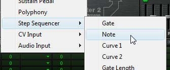
Step Sequencer > Note: This is one other way you can source Key scaling, however, this setting sources the note data directly from the sequencer. It’s similar to the “Last Key > Note” setting, except while “Last Key > Note” can accept both MIDI & Step Sequencer note data, the “Step Sequencer > Note” source can only accept Step Sequencer note data.

As with setting up Velocity parameters using the MBRS, you can extend the range of Key Scaling parameters. For example, if you apply the highest LFO 2 rate to control another Thor parameter, and then create 3 identical lines in the MBRS as follows: Key Note : 100 > LFO 2 Rate, you can extend the range of the LFO 2 rate to about 400% (The LFO 2 Rate knob (100%) + 3 MBRS rows (300%) = 400% of the LFO 2 Rate in total). Anything beyond this seems to result in a point of no return. I’m not completely certain how this would work for the filter or oscillator key tracking, but it’s probably the same theory. Of course, once a filter is “open” or “closed,” there’s no further you can go with it. So there are limitations.

Key Scaling Strategy

Most times I am trying to get the widest possible usable range out of a sound design. Here is the strategy I employ when attempting to do this:

First, I always think of the baseline at middle “C.” If you are working with a single Oscillator, this means you first set the Tuning (Octave / Semitone / Tune) knobs to play your intended sound design or sound idea at Middle “C.” If you have more than one Oscillator in the mix, set their tuning up as well, and ensure that they are tuned to work together to produce the sound you intend the musician to play at “Middle C.”

Once you set the Oscillator(s)  baseline, move to the filters, and ensure you have the filter frequency and resonance set up correctly for the same sound played at middle “C.” Same goes if you have the LFOs modulating any of the Thor parameters. In essence, set up your baselines first.

Once that’s done, start adjusting the KBD tracking for the Oscillators, Filters, and LFOs. Play the patch at the bottom end of the keyboard and adjust the settings until you hear the sound you want. Once that sounds the way you want, move to the upper end of the keyboard and play the patch up high. If it sounds good to you, then you’re done.

However, at this point, if the patch sounds too bright, for example, you may need to adjust the Filter frequency knob or the Filter KBD knob. It’s at this point that things can become tricky. The reason is that modifying key scaling affects the entire range of the keyboard. If you change the key tracking settings at this point, you are changing them for both the low and high end at the same time. What affects the bottom will affect the top. So any changes you make at this point will force you to test out the patch at the bottom end of the keyboard again. It’s a bit of a balancing act and you may need to make a few compromises. But the goal should be to try to get the widest usable range for your sound construction out of your keyboard.

Aftertouch

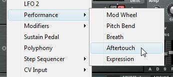
Aftertouch, or “pressure sensitivity” is employed after the key on your keyboard is initially struck, and allows you to modulate a synth parameter based on how hard you press the key (during the sustain phase). You can, for example, modulate a filter opening or a slight positive amplitude based on aftertouch. This will force the sound to gradually brighten or become louder the harder you press on the keys. As I stated in Part 2 of this series, not all keyboards come equipped with Aftertouch, but you should still try to employ it in your patches to make the sounds respond more dynamically to the musician’s playing style. Once again, all the same rules that apply for Velocity and Key Scaling also apply for Aftertouch. The only difference where Thor is concerned, is the fact that there is no “fixed” control for Aftertouch on the Thor panel. To program Aftertouch into your patches, you’ll have to use the MBRS and create a destination or multiple destinations for the Aftertouch parameter. But since I’ve explained how the MBRS works, you should now be a pro at how to do this. 😉

The Performance > Aftertouch setting in Thor's MBRS source submenu

So that does it for the keyboard performance parameters. In the next series, I’ll go through the Wheels, Buttons and Rotaries you can use in Thor. In the meantime, please let me know if you have any ideas that come out of these tutorials, or if you have any tricks to teach us when it comes to Key Tracking and Aftertouch. I’m always looking to find new sound design techniques. Happy Reasoning!

75 – Creating Better Patches (Part 2)

In this second installment of Reason 101’s Guide to creating better patches, I’m going to focus on Performance, Velocity, and how the MBRS (Modulation Bus Routing Section) in Thor relates to both. The focus is to look at new creative ways you can improve how Thor reacts to your playing style and explain some of the reasons why Thor is such a powerhouse of flexibility in this area. Again, I’m not going to be approaching this as a complete guide to every possible performance technique you can accomplish inside Thor, but rather try to outline its flexibility and show you a few key aspects of performance that you should think about as you develop your own patches.

In this second installment of Reason 101’s Guide to creating better patches, I’m going to focus on Performance, Velocity, and how the MBRS (Modulation Bus Routing Section) in Thor relates to both. The focus is to look at new creative ways you can improve how Thor reacts to your playing style and explain some of the reasons why Thor is such a powerhouse of flexibility in this area. Again, I’m not going to be approaching this as a complete guide to every possible performance technique you can accomplish inside Thor, but rather try to outline its flexibility and show you a few key aspects of performance that you should think about as you develop your own patches.

What is Performance?

Performance has less to do with the actual sound than it does with how the sound is played. If sound is the Motor that moves the car, Performance is the route it takes. It adds dynamism, movement, and modulation. And it is just as important as the actual sound you are hearing, or in our case, “creating” inside Thor. Both the sound and the performance of the sound are intrinsically interconnected. Without performance, sound would be very lifeless and dull, devoid of any movement or humanity. In terms of creating a patch in Thor, there are several performance parameters that you can use to determine how the sound is affected (changed or modulated) based on the way the patch is played by the musician. It is up to you, as a sound designer, to select what changes are made to the sound when a key is struck softly versus when the key is struck hard. It is up to you to determine what happens to the sound when the patch is played at different pitches along the keyboard, or when the Mod Wheel is used. And Thor offers an endless variety of ways you can harness the power of performance.

Performance Parameters

Performance parameters fall into the following categories (note the names in parentheses refer to the different names these performance parameters are given on the front panel of the Thor synth):

  • Velocity (or Vel): How soft/slow or hard/fast the keys on your keyboard are initially pressed.
  • Keyboard Scale (or “KBD,” or “Key Sync” or “KBD Follow”): The Keyboard register/pitch, or, where you play on the length of the keyboard (from -C2 to G8)
  • Aftertouch: Also called “Pressure Sensitivity,” Aftertouch responds to the pressure you place on the keys after they have initially been pressed down.
  • Mod (Modulation) Wheel: A unipolar (0 – 127) wheel that is generally used to (but not limited to) control vibrato (pitch wobble), tremolo (amp wobble), or both.
  • Pitch Bend: A bipolar (-8,192 – 8,191) wheel that is generally used to (but not limited to) control the pitch of the sound upward or downward.
  • Breath: Used with a breath or wind controller. Breathing into the controller will usually cause the sound to be modulated in some way. And if you’re interested in how a breath controller can be used, check out http://www.ewireasonsounds.com/ and http://www.berniekenerson.com/
  • Expression: Usually this parameter is tied to an Expression Pedal, usually found on an organ or piano.
  • Sustain Pedal: Usually this parameter is tied to a Sustain Pedal, usually found on an organ or piano.

Note: While performance relates to how the physical instrument / MIDI Controller is played by the musician, any performance parameter can also be programmed or automated in the Main Sequencer in Reason.

The various Performance parameters that can be assigned in Thor's MBRS.
The various Performance parameters that can be assigned in Thor's MBRS. Note the Sustain Pedal is located in the root folder, not within the Performance subfolder. Velocity is under the "MIDI Key" subfolder, and Keyboard Scale is found at the top of the root menu under the "Voice Key" subfolder.

While all these parameters can be “turned on” or “turned off” (“implemented” or “not implemented”) in a patch, generally you want to make use of most of these parameters in order to make your patches highly flexible and dynamic. However, I don’t use the Breath, Expression, or Sustain Pedal controls. To my mind, these three controls are very specific, and unless the Musician has a pedal or a wind controller (like a MIDI Flute), they won’t be able to make much use of them. If I were designing a ReFill specifically for a Wind Controller, however, then the Breath parameter would be extremely important and you would probably design most of your patches with this type of control in mind. But for the majority, these controls probably won’t need your attention. And I won’t be discussing them here.

Out of the remaining controls, you can break them down into two groups:

A: Keyboard controls: Velocity, Keyboard Scale, and Aftertouch. These are the Performance parameters that rely on how you play the keys on your MIDI keyboard. Velocity and Keyboard Scale are vital in my opinion. Aftertouch is not as vital, since not every MIDI Keyboard controller can utilize Aftertouch. But many CAN utilize it, and as a designer trying to make your patches stand out, this is one area that can separate your patches from others; making them shine. Note: If your keyboard is not equipped with Aftertouch, you can still test your patches by creating an aftertouch automation lane in the Main Sequencer in Reason, and drawing in your automation. This is true of any of the above Performance parameters. However, this kind of testing can be rather tedious. Better to try and purchase a controller that comes equipped with Aftertouch capability if you can spare the money.

B: Wheel controls: Pitch Bend and Mod Wheel. These are the Performance parameters that rely on how you play the two wheels on your MIDI controller. It’s rare you will find a MIDI keyboard that doesn’t have these two control wheels as commonplace controls, so it’s always a good idea to design your patch with these two controls assigned to modulate something in your patch. Furthermore, even if you don’t have a keyboard controller that has these wheels, you can still test the controls by turning the Thor wheels up or down on-screen with your mouse.

Let’s start with the Keyboard controls:

Velocity

Think of a sound that has no velocity sensitivity. You actually don’t need to travel too far to think about it. Load up a Redrum, set the Velocity switch to Medium, and enter a Kick drum that beats on every fourth step (typical four to the floor programming). Now play the pattern back. Sure, the drum sounds great, and it has a beat. But it has no change in level. It’s as lifeless as a bag of hammers.

Now put a high velocity on the second and low velocity on the third drum beats. Listen to the difference. Obviously this is still pretty lifeless, but by introducing Velocity, you’ve introduced a small degree of movement to the pattern. It’s more dynamic “with” velocity than “without” velocity. It doesn’t sound stilted or robotic. It starts to take a better shape. You’ve just added a performance characteristic by changing how the sound is played, albeit, you’re programming the velocity instead of playing it on a keyboard.

Now instead of putting the Kick drum through Redrum, what if you built your own Kick drum in Thor, and played it from your MIDI controller, Your keyboard is capable of a range which goes from 0-127, so you can have 127 different degrees of Velocity (or put another way, you have 127 different velocity levels). When you strike the keyboard to play your Kick drum, the “Velocity” at which you strike the keys can be used to determine the amplitude of your Kick Drum sound.

Velocity in Thor’s MBRS

Now here’s where things get interesting, and Modular / Semi-modular, in Thor terms. Thor offers both hard-wired (fixed) routings, and programmable (adjustable) routings. What you see on the front panel of Thor is what I would term as “Fixed,” while the Modulation Bus Routing Section (the green area below the front panel) offers you the ability to create your own custom routings; not just audio routings, but also performance routings. Using the MBRS, you can adjust what these performance characteristics will affect in an incredibly open-ended way. In other words, you can use any of these performance parameters to change any other Thor parameters you wish (within a few limitations).

Now let’s look at a fundamental use of Velocity in Thor.

Velocity = How soft or hard you play your keyboard. How the note is performed.
Amplitude = The amplitude or volume of a note. How soft or loud the note sounds.

By combining these two parameters together, you end up with the following:

Velocity Amplitude = A change in amplitude when you play your keyboard soft versus hard. Put another way, the “Velocity” is what is “performing the change” while the “amp” is “being changed.” Velocity is the “How” and Amplitude is the “What.” Velocity is the “Verb” and Amplitude is the “Subject.” Or put in Thor terms, Velocity is the “Source” and Amplitude Gain is the “Destination.”

I’m stressing this concept for a very good reason, because it’s the basis of all modulation concepts inside Thor (and any other really good modular synth for that matter). The main reason why people go kookoo for cocoa puffs over the MBRS in Thor is because you can change the “Verbs” and “Subjects” around in any wacky way you like. So any of these “Performance Parameters” can be used to change any other “Thor Parameters.” And not just that, but you can have as many “Verbs” affecting as many “Subjects” as you like. Or have one “Verb” affecting many “Subjects” or have many “Verbs” affecting one “Subject.” The only limitation to how many routings you can create is the number of MBRS rows provided in Thor.

At this point, you might want to know the complete list of Verbs and Subjects right? No problem. In the MBRS, click on the first “Source” field. Those are your “Verbs.” Now click on the first “Destination” field. Those are your “Subjects.”

Typically, you want your Velocity to affect the amplitude in such a way that the softer you press the key, the lower the amplitude is, while the harder you press the key, the higher the amplitude is. But what if we want to reverse this relationship. What if we want softer key strikes to result in louder sounds, and harder key strikes to result in softer sounds. We can very easily accomplish this in Thor using the “Amount” field in the MBRS. Since you can set up the amount to go from -100 to +100, you can make the Velocity affect the Amplitude by a “positive amount” or a “negative amount.” Here’s how both Velocities would look inside the Thor MBRS:

First, turn down the Velocity and Amp Gain knobs on Thor’s front panel, so they are fully left. Then Add the following routing in the first line of Thor’s MBRS:

Positive Velocity Amplitude = MIDI Velocity (Source) modulates by +100 (Amount) to affect Amp Gain (Destination)

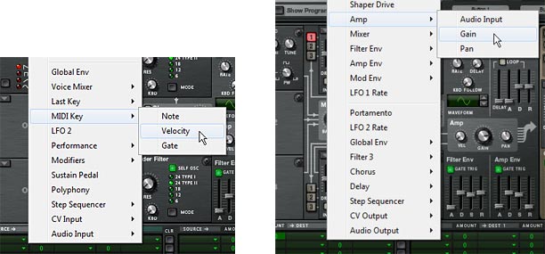
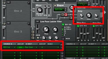
The Source (MIDI Key > Velocity) and Destination (Amp > Gain) settings in the MBRS row

Next, turn the Amp Gain knob up, fully right. Then change the amount in the MBRS line you previously created, as follows:

Negative Velocity Amplitude = MIDI Velocity (Source) modulates by –100 (Amount) to affect Amp Gain (Destination)

I’m sure by now you’ve noticed that the amount does not necessarily need to be exactly 100 in either direction. You can, of course, enter any amount between -100 and +100 as well. What happens if you lower the Positive Velocity Amplitude? You end up with Velocity affecting the Amp Gain to a lesser degree. In this respect, Amount is actually a way to “Scale” back on the Amp Gain when Velocity is used.

Now what if you want Velocity to affect Amp Gain some of the time, but not all the time? For example, I want to create a patch where the performer can use Velocity some of the time, but not all the time. You can create an on/off switch for this very easily using the “Scale” parameter in the MBRS. Just add the following:

Positive Velocity Amplitude = MIDI Velocity (Source) modulates by +100 (Amount) to affect Amp Gain (Destination)

and this Positive Velocity Amplitude modulation is scaled by +100 (amount) from the Button 1 (Scale) control.

Put another way:

PVA = [MIDI Vel (Source) modulates +100 (Amount) to affect Amp Gain (Destination)] scaled by +100 (Amount) from the Button 1 (Scale) control.

In the grand scheme of things, Sources and Scales are the same. Anything that can be used as a source can also be used to Scale a modulation. The only limitation is that you can’t have a “per voice” parameter scale a “global” modulation. For example, you can’t have the Modulation Envelope Scale the LFO2 Source changing the Global Envelope Attack. Anything that is “per voice” is considered anything in the “black area” on Thor’s front panel, while anything “global” is located in the “brown area” on Thor’s front panel. There’s also a line that separates the “Per Voice” parameters from the “global” parameters in the menu that opens when you click on “Source,” “Destination,” and “Scale” fields in Thor. “Per voice” parameters are located above the separator, while “global” parameters are located below the separator. If you choose a global modulation to scale a per voice modulation, a strikethrough line will appear over the text in the MBRS row.

Now, when Button 1 is turned on (lit up), the Positive Velocity Amplitude is active for the performer. When the Button 1 is turned off, the Positive Velocity Amplitude is inactive. By now, I’m sure you have figured out that you can reverse this “Button 1 on/off behavior” by reversing the Scale amount to -100. This would mean the PVA is active when Button 1 is off, and inactive when Button 1 is on.

You might also want to provide “degrees” or “gradations” of changes in the way the PVA is modulated. If this is the case, change “Button 1” to “Rotary 1” and then use the Rotary to provide 127 shades to how “active” the PVA modulation is. The more the Rotary is turned right, the stronger the effect of the PVA becomes. The lower you turn the Rotary, the less impact PVA will have on the performance. How you set this up is totally up to you, the sound designer.

Important Point: Your setting in the MBRS works “in conjunction with” the fixed parameters in the Thor synth. This means that the amount of your Amp Gain knob is going to determine how the routing you’ve set up for it in the MBRS operates. If the Amp Gain knob is set to zero (0) on the front panel, and you’ve set up a Positive Velocity Amplitude as shown above, the knob has no effect, and the MBRS settings are doing all the work to control the Amp Gain. If, on the other hand, you turn up the Amp Gain knob, the sum of the knob’s gain position is added “on top of” the amplitude increase you’ve set up in the MBRS. It is cumulative. This is why you need to adjust the “Amp Gain” knob in the above examples, even when you enter the MBRS settings. The fixed “Amp Gain” knob setting works in conjunction with the adjustable MBRS “Amp Gain” routing assignment.

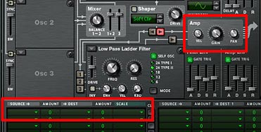
In this setup, the Amp Gain is completely controlled via the MBRS routing, since both the Amp Gain and Velocity knobs are turned all the way down (fully left).

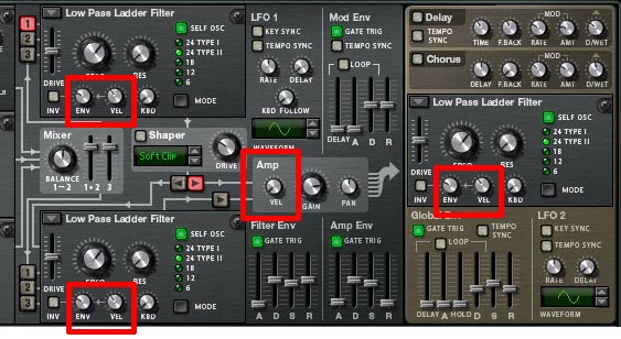
Now that you know a little bit about how the MBRS works, I’m going to completely throw all of the above away, because you don’t have to set any of this up in the MBRS at all. Notice the little “Vel” knob next to the Amp Gain knob? This is an example of one of those “fixed” elements of Thor. And since a “Positive Velocity Amplitude” is such a basic principle in most sounds or patches, The Propellerheads gave it a “fixed” position in Thor, next to the Amp Gain knob. By default, it is turned down or off, but you can raise it (turn it right) to achieve the same effect as if you created a line for it in the MBRS.

In this setup, the Amp Gain knob and Velocity knob are controlling the Velocity, not the MBRS. The velocity control result is exactly the same as in the previous image. It's just a different way to set it up within your patch.

Also keep in mind that since both the “fixed” parameter (the Velocity knob) and routing (the MBRS) work in tandem, if you have the Velocity knob set to 127 (fully right), and have a line in the MBRS set up for Positive Velocity Amplitude as outlined above, you are essentially doubling the degree to which your Velocity is affecting the Amp Gain (+200). Same goes if your Velocity knob is set to zero (0), and you create two lines in the MBRS that both have Velocity affecting the Amp Gain by +100. If you duplicate lines in the MBRS, you ARE going beyond a value of 100, and this is true if you go in a positive or a negative direction. Lastly, if you have the Velocity knob set to +127 and the MBRS is set to -100, then they cancel each other out, and Velocity DOES NOT affect Amp Gain at all.

It should be noted that there are actually three different Velocities that can be used as a Source or a Scale in Thor. Here’s how they differ:

  • Voice Key > Velocity: This setting sources velocity on a “per note” basis. In this respect, it’s the most granular of the Velocity settings in Thor. Each note polyphonically will receive a different Velocity setting based on how soft or hard you play each key. Of course, if you use this setting, you probably also want to be using a polyphonic patch that has more than one voice. Otherwise, it will react the same way as the MIDI Key > Velocity setting.
  • Last Key > Velocity: This allows you to use the Step Sequencer or incoming MIDI key signal to source Velocity. This is also global, so it is also “monophonic” by nature. The idea is that the last key played (from either the Step Sequencer or the MIDI Key) determines how the velocity is sourced.
  • MIDI Key > Velocity: This sources the Velocity globally via the incoming MIDI key signal. It is different from the Voice Key Velocity setting because it is monophonic, and it is different from the Last Key Velocity because it does not react to incoming signals from the Step Sequencer; only incoming MIDI signals (ie: a keyboard controller).

So before you start assigning Velocity settings, think about how your patch will be played by the musician. If your patch is programmed via Thor’s step sequencer, then you will need to use “Last Key Velocity.” If you want Velocity to be accessed via the MIDI Keyboard, all three settings will work, but you have the option to set up velocity on a per-note basis using “Voice Key Velocity” or on a global basis using “Last Key Velocity” or “MIDI Key Velocity.”

Beyond Typical Velocity Settings

Up to this point, all we’ve accomplished is how to create one simple performance parameter in the MBRS which is used the majority of the time in most patches in one way or another: Positive Velocity Amplitude. And yet I can’t tell you how many times I’ve seen patches that don’t even go this far. No, I’m not going to name names. But my point is that if you do anything at all in your patches, at the very least turn up the “Vel” knob next to the Amp Gain at least a little bit. Or keep the Filter envelope and velocity settings at their default in order to create a little movement in your patches that are tied to Velocity. Sure, there are cases where Velocity does not effect Amp Gain, and even cases were Velocity is not used at all. There will always be exceptions. But if you do anything at all, use the velocity knobs that Thor is giving you in the main panel. This will bring your patch designs from Noob to “Beginner” or “Good” as far as Velocity goes. Don’t forget to think about Velocity! It can be of the most expressive of qualities of your patch, and it adds yet another dimension to your patch that shouldn’t be overlooked.

Now if you want to make your patches go from “Good” to “Great” might I suggest getting your feet wet in the MBRS and experimenting with the following ideas:

  1. Change the destination around. What if we have Velocity affect the Filter Cutoff, or the FM Frequency, or the Mix between Oscillator 1 and 2? The point is, try it out for yourself and see what creativity you can come up with. See if it enhances your sound or detracts from it.  Remember that you are not limited to tying volume to velocity.
  2. Test out the “Amount” setting when you are creating an MBRS routing. Sometimes a negative value will produce a better result than a positive one. If a velocity setting produces a very harsh jump in modulation from soft to hard key presses (or vice versa), you might need to scale back the amount to a more comfortable setting.
  3. Try having the Velocity affect more than just a single parameter. Have Velocity affecting both the Filter Cutoff and the Filter Resonance at the same time. Or perhaps, if two filters are used, have the Velocity setting open up one filter (positive amount) and close the other filter (negative amount). This creates something akin to a Filter Crossover.
  4. Try assigning different destinations to the “Voice Key > Velocity” and “MIDI Key > Velocity” sources. I haven’t tried doing this yet, but I would imagine it can create some very interesting Velocity-sensitive sounds, since one is “per voice” and the other is “global.”
  5. Something I’ve been experimenting with lately is having the Velocity affect the Rate of an LFO, and then having the LFO affecting another parameter in Thor. This has the effect of creating a slow modulation on one end of the velocity spectrum and a faster modulation on the other end of the spectrum. Using positive amounts, when you press the key softly, the LFO is slow, and when you press the key hard, the LFO speeds up. Using negative amounts will reverse the process.
  6. Velocity is independent of the Amp Envelope. Whereas the Velocity is a measurement of how soft or hard you press the key (a function of Weight+Speed on the keys), the Amp Envelope is a measurement of loudness over time. That being said, Velocity occurs before the Attack portion of the Amp Envelope, and therefore, it can be used as a source to control the Attack, Decay, or Release portion of the Amp Envelope (or any other envelope) in Thor. Try using Velocity to change these aspects of your patch. It can produce interesting results as well.

So go make some killer patches and practice changing the destinations and the amounts, so that you hone in on just the performance quality you want out of your patch. And ensure that you keep testing using your Keyboard Controller. Play your patches at low velocities and high velocities as you create modulation routings so that you can hear the effect Velocity has on your sound.

Note: Most Keyboard Controllers have built-in velocity sensitivity and even come with specialized settings that allow you to select from different Velocity scales, depending on your playing style. But before you begin, ensure your keyboard IS velocity sensitive. In the rare case that it is not, you can press F4 (in Reason 6) to access the on-screen keyboard. Using the keyboard, you can switch between velocities. It’s time-consuming to test this way, but I would be remiss if I didn’t mention it as an option.

Fixed Velocities in Thor

In Thor, there are essentially two types of “Fixed” Velocities. I’ve already discussed the first fixed velocity as the “Positive Velocity Amplitude” which is otherwise known as the “Vel” knob in the Amp section of Thor. So I won’t go into detail about that. But there’s also another kind of Velocity which is located as a knob on all Filters in Thor. This is what I like to call the “Positive Filter Envelope Velocity” knob. This sets how much the velocity you play on your keyboard affects the envelope of the Filter. Think of it as having Velocity affecting the Envelope. If the envelope is set to zero, the Velocity knob has no effect on the envelope. Nothing happens. If your envelope is turned higher, and Velocity is turned up to 100, for example, the Velocity you play will have a pretty significant effect on whether or not you hear the envelope affecting the filter. Sounds complicated, but test it out by creating a very noticeable Filter envelope, and then turning up both the envelope and velocity knobs, then play your key controller softly and very hard. Notice the difference?

The Fixed Velocity settings in Thor.
The Fixed Velocity settings in Thor. Note that you can turn off these fixed Velocities very easily by turning all the Velocity knobs fully left. This frees you up to set up your own velocity routings in the MBRS, as you see fit.

So that does it for the second part of the series. I’ll continue with the other Performance parameters in part 3. As always, if you have any questions or want to contribute your thoughts and ideas, I encourage you to do so. I’m always interested in hearing new ways you’ve found to work with Reason. All my best until next time.

74 – Creating Better Patches (Part 1)

As a sound designer, your job is to create sounds for others to utilize in their own compositions. There’s immense satisfaction to be gained on both sides as the artist gains access to a myriad of new sounds, and you, as a sound designer, get to benefit from hearing how others are using your sounds (and remuneration for your time and effort creating them is always a plus). So in this article, I’m going to explore some ways you can A) Make your patches more usable by the artist, and B) Think more creatively about the art of patch design.

As a sound designer, your job is to create sounds for others to utilize in their own compositions. There’s immense satisfaction to be gained on both sides as the artist gains access to a myriad of new sounds, and you, as a sound designer, get to benefit from hearing how others are using your sounds (and remuneration for your time and effort creating them is always a plus). So in this article, I’m going to explore some ways you can A) Make your patches more usable by the artist, and B) Think more creatively about the art of patch design.

You can download the project files here: zero-initialized-patch-files. This zip file contains the Reason 6 setup for creating a Thor patch. It also includes a few fully initialized patches for the various Reason devices. These patches, as explained in the tutorial below, can be used as a starting point to create a basic patch in all three of the Reason synths. The patches are used to force every parameter to “zero” or “off” so that you can truly start the patch creation process from a completely blank slate. To this day, I still use this method when starting a new sound or patch design. It may take a little longer to set up. But it ensures I’m not colored by any settings that are already input into the device, and ensures I think about the whole audio signal as I go.

This article is not about every single patch design possibility. You could literally write several books on the subject and still not be finished. Instead I’m going to focus on a few key areas that are important and may open you up to some new sound design possibilities. For this series of tutorials, I’m going to focus on Thor, and show you some of its flexibility. Being the flagship synth of the Reason software, it deserves more attention than the other synths. It also has a steeper learning curve than the other synths (not to say the other synths aren’t very powerful. They are! But Thor is just so much more flexible in a lot of ways, mainly due to it’s semi-modular design).

I’m also going to assume that you know a little bit about what an Oscillator, Envelope and Filter does, and you’ve worked a little bit creating your own sounds. If you’re unfamiliar with these basic synth concepts, then start off reading the Reason Manual (start with the Subtractor section), or else go online to Wikipedia and get familiar with the basic building blocks of sound and sound modulation. Then come back and see if this makes a little more sense to you.

Also please take this series of articles with a grain of salt. Sound design is very subjective and encompasses a wide range of styles, approaches, likes and dislikes. This is not gospel. This is just some of the ways I go about creating my patches. You may have your own methods which are just as valid as mine. There’s no right or wrong (except that you don’t want any patches to clip or have a volume that’s too hot – this is pretty much golden no matter who you are).

The Checklist

Before jumping into some of the basics, here is a checklist you can use to ensure you make the most out of your patches and sound designs. This breaks everything down into a few important sections. When I’m designing a sound, I’m always conscious of the following:

  • What sound are you creating (optional): Sometimes you want to get in there and create a Bass, other times, you just want to experiment and see what you come up with, without having a preset notion of the end sound design. Both approaches should be explored, and is totally up to you.
  • Amplitude: Ensure the patch is in the general range of -6 dB when the big meter is set to peak / peak mode. Never let the patch clip (go into the red).
  • Performance Assignments: Ensure that rotaries, buttons, and wheels have assignments. Brownie points for Velocity, Aftertouch, and Key Scaling (if needed). Provide the most functionality or flexibility you can for the user in each and every patch.
  • Labels: Ensure all the rotaries, buttons, patch names, and ReFill Folder names and structure, are logical, useful, or make sense. Bonus points if you can make the labels have meaning both on a functional level (what I call the “engineering”) level, and on a descriptive level (what I call the “Plain English” or “Layman’s terms”) level. For example, the label “LP Filter” is functional. The label “Brightness” is descriptive. So perhaps you can combine them and call the label “LP Brightness,” which can make it a more useful label. Remember when you are creating patches for others to use, the label is often the only documentation provided with a patch. So make it count.
  • Documentation: You may find that a patch you create requires some user documentation. Situations where this can come in handy is if you want to further explain the interaction between rotaries/buttons, how to use the Mod Wheel or Performance during play, if a patch is designed for a specific key range and what that range is. Providing extra documentation can help make you go from a good patch designer to a great patch designer (even if the majority don’t read the documentation). That being said, in general you should always try to design your patches to have the most flexibility possible. And documentation is no substitution for intuitive patch design. The more intuitive and interesting you can make your patches, to the point where anyone who opens them can start playing and use them without documentation, the further along the road to “great” patch designer you are.
  • Creativity: No, there’s nothing under the sun that hasn’t been done before. True. But be creative. Try out new methods and think outside the box. How about applying the rate of an LFO to the Velocity, or adding FM between two oscillators to the Aftertouch setting? What about changing Delay Feedback at the same time you open up the Filter Frequency and attaching that to a Rotary? There’s a million different approaches, combinations, and ideas. Do something that sets your patches apart from everyone else.
  • Did you create the sound you wanted? Is there anything you would change to make it better? This is the final stage where you review the sound and ensure that everything makes sense, and that things sound the way you want them to sound. Often times, I’ll put down the patch or else create a series of patches and then leave them alone for a few days, and then come back and listen to them again. Often times this can shed light on a few areas that could be tweaked or rewritten to make the sounds better. I might change assignments from the Mod Wheel to aftertouch or velocity. I might find a sound is too harsh, so I’ll filter it a little more. This is where you put the finishing touches on your patches, just as you would perform final EQ adjustments to your songs.

Amplitude & The Big Meter

First, let’s start with the Level / Amplitude of your patch. While I know everyone has their own opinion on what the “correct” level of a patch should be, unless I’m designing something solely for myself, and solely for a specific reason, I generally open up the Big Meter in Reason’s Hardware Interface, set it to VU+PEAK mode, and ensure the levels of your patch do not exceed approximately -4 dBFS (VU) or -6 dBFS (Peak). This is dependent on a lot of factors of course, and the meters are only an aid to help you. They are not meant to replace your ears. If the patch sounds right, then it IS right. But one thing is for sure: you don’t want the meters going in the red. EVER! This means your signal is clipping, and should be avoided. Better to be too cautious than too aggressive in your sounds.

Note that clipping occurs when you see the Meter go into the red. With Reason’s default settings, this is a value of 0 dBFS (VU) or 0 dBFS (PEAK). Ensure that your audio signal is always consistently below these values, no matter what performance parameters are used in the patch, and no matter what combination of these performance parameters are used (more on this below).

If you’ve never worked with meters before, it helps to understand how they work and what they are telling you. Without getting bogged down in the theory behind them, here’s the bare bones of what you need to know. First, the video:

Next, the quick discussion: All 3 meters are explaining the same thing, but in different ways. The VU (Volume Unit) meter is averaging a period of time, and so provides you with an average volume level for what you’re monitoring. The PEAK meter, on the other hand, is providing you with an instantaneous Peak level for what you’re monitoring. It may seem from reading this that the VU meter isn’t accurate for measuring clipping, but this is not entirely true. While PEAK is a better indication of the actual highest point of your audio level, the VU meter is closer to what the human ear perceives as loudness. Therefore, it has value when creating your patches. For example, you may have a sound without a loud peak, but with a very loud average volume (for example, long sustained pad sounds). This can lead to a patch that seems too loud when you hear it, but still doesn’t clip. Or you may have a sound that has very high peaks, but seems too soft to your ears (vocals and transients can easily fall into this category). These two meters can help guide you to see that you’re on the right path. The following explores the way the Big Meter operates in Reason (the down and dirty “Coles Notes” version):

The Big Meter and its associated parameters.

Here’s a quick tutorial to set up the Big Meter to monitor your patch sound designs:

  1. First, click on the Audio I/O and Big Meter buttons in the Hardware Interface. This opens both, and expands the Big Meter below the Audio I/O.
  2. Next, click the little square below Audio Output 1/2 (or whichever audio output you want to monitor). Alternately, use the Big Meter Channel knob to turn the Big Meter’s focus on the proper output.
  3. Using the Big Meter Mode button, adjust until you have VU+PEAK mode selected. Now you can monitor your audio using both meters. VU is listed in light blue along the top of the Big Meter scale, and PEAK is listed in orange along the bottom. When viewing the audio output LED lights on the Big Mixer, note that the VU LEDs are always to the left of the PEAK indicators. And the Peak indicators are displayed as two LED lights to the farthest right. It takes a little getting used to, but it’s a valuable way to monitor your sound and ensure there is no clipping.
  4. Ensure the Peak Hold is set to Five Sec (to indicate that the PEAK setting readjusts after every 5 seconds).

In addition, setting the amplitude of your patch revolves around several interrelated aspects of your patch: The big Volume knob, How many Oscillators are being used, the Polyphony setting, how they are routed, the Mix between them, The Decay / Sustain setting of the Amp Envelope, the Gain setting of the Amp section, the Filter Drive settings, and even the Filter Frequency and Resonance. All of these factor into how loud your patch sounds, and whether or not it’s clipping. In fact, everything you do in your patch will affect the amplitude one way or another. That’s just the nature of the beast.

Generally speaking, I adjust most of the amplitude levels during patch creation; as I go, since most changes you make to a patch will affect amplitude in some way. So I’m forever adjusting and tweaking the levels as I create the patch. However, I tend to work from the inside out. I’ll adjust patch settings inside the Voice and Global sections of Thor first, making sure those settings are correct. Then I may make an adjustment to the main level of the Thor patch via the big Volume knob after the patch settings are in place. In addition, I usually (but not always) work by following the signal flow. For instance, I’ll first adjust the drive setting of Filter 1 before adjusting the Gain setting of the Amp section inside Thor. This helps to get the levels correct, and also helps to understand the signal flow of the patch you’re creating.

Testing Amplitude During Performance

I categorize the Polyphony, Envelopes, Velocity, Aftertouch, and Key Scaling settings in this group of volume control. I generally know in advance if I’m going to be creating a patch that is monophonic versus Polyphonic. And if the patch is monophonic, I set the volume levels while playing a single note at maximum velocity. If the patch is polyphonic, I’ll adjust amplitude settings based on playing a 3- or 4-key chord at maximum velocity. It’s also important to play the patch up at high registers and down at lower registers to see if the volume is consistent across the entire keyboard. Often times, a synth that has a proper volume in the C2 and C3 range, can be overly bright at higher registers (which can increase the volume), or can overload the bottom end amplification-wise. Without getting too deep into this conversation, just keep in mind that the number of voices (polyphony) affects amplitude, and should be tested accordingly.

The envelopes you set up for the Oscillators are also important. The sound can start off low, and then build up over time to peak much higher than your maximum. So if you’re creating a long drawn-out pad sound which develops over time, be sure to listen and monitor the sound played over the entire duration of the envelope and check that big meter to make sure you don’t go too high.

And not to make things even MORE complicated, but if you have set up your rotaries, buttons, mod wheel, aftertouch, and velocity settings to certain parameters, it’s very important that you test out all the possible combinations of these buttons and performance settings and see how they all interact together. Often times, when you create a patch, you’ll test out the sound while turning Rotary 1 front and back, but have you tested how Rotary 1 sounds when Rotary 2 is turned front to back as well? Or when button 1 is on, etc. You can easily end up in situations where Rotary 1 sounds perfect on it’s own, but introduce Rotary 2 and all of a sudden the patch is clipping. So be very cautious of that.

It’s important to understand that all of these settings inside Thor affect the amplitude and are interconnected, playing off each other. Balancing out the amplitude while getting the sound you want is one of the primary keys of good sound design. So when you’re first starting out, don’t be afraid to push the limits and see how turning up the filter drive affects the sound, or turning down the gain while turning up the Filter 3 drive changes the sound. But be cautious about good balance. Generally if you turn up one amplitude setting, this will mean you have to turn down another setting somewhere along the audio signal chain. This is where the Big Meter can help you understand how the various parameters you set affect the amplitude. After a while, you may find you don’t need it at all.

Volume Consistency

There’s also one other reason to pay close attention to the volume level of your patches: Consistency. You don’t want one patch to be extremely loud and the other patch to be extremely soft. You want to provide some degree of consistency across your patches, and indeed your Refill.

For me, a good consistency is when the patches are all somewhat close to each other in volume, both average volume and without causing any peaks to clip. Of course, this will also depend on the type of instrument you’re creating, the frequency range of the instrument, the rise and fall of the Amp Envelope, etc. But you still want them all to be somewhat consistent relative to each other.  Make it easy for the user to use your patches. Providing consistency will help do this.

Note: A good test to see how accurate your ears are is to turn off the big meter entirely, and hide all the metering (put a piece of tape over the metering displays on your monitor if you have to). Design a few different patches in Thor without the aid of any metering. Then go back through the patches and see how close you came to getting the patches all set to consistent levels.

In summary, it’s a good idea to think of Volume and amplitude in your patches as a system of pulleys and levers that need to equalize at the outcome. If you pull one lever up, you generally need to pull another level somewhere in the audio chain down. Kind of like balancing a budget. If you spend more in one area, you have to save in another. Thinking in these terms will help you come out with a better patch in the end, which is consistent with your other patches. When you produce a refill, getting the levels even across the board is very important, and it’s something that will make your ReFills better in the long run. So take a minute to explore how volume is affected when you change things around in your patch, and learn to compensate when you raise that drive on that filter.

Setting up your Thor patch

Now that we’ve got the basics out of the way, let’s fast forward to looking at how you can assign some parameters in Thor. What I tend to do when starting any new patch is to “zero out” all the parameters. This means I don’t start from the typical “Init patch” assigned to the device. Instead, I’ve created my own set of “True Init Patches” for each of the devices. This means all the sliders and levers are dropped to zero, all the buttons are turned off, and there are no assignments anywhere. I do tend to leave the polyphony setting to “1” voice for “polyphony” and “1” voice for “release polyphony” — I can always add more voices later. Furthermore, I remove all the labels for the rotaries and buttons. Starting from this blank slate is worthwhile for two reasons:

  1. Starting from “zero” does not influence the direction I am headed when creating a sound or patch. With the typical “init patch” setting in Thor, for example, I might be influenced to create a sound which uses an analog oscillator and low-pass filter, and keep the settings for the envelopes as they are. If, on the other hand, you start out with a completely blank slate, there is nothing that is previously set to color the direction of your patch creation. This may not be your style, but I find it very refreshing to start with a blank piece of paper when writing something, as opposed to starting somewhere midway in the story, where the introduction has already been written.
  2. Second, if you are new to synthesizers and sound design, starting from ground zero forces you to learn what each setting does. And it forces you to learn one step at a time. You’ll soon learn that without an Oscillator and Amp envelope turned on in Thor, you won’t hear a sound. But forcing you to turn it on will force your brain to make the connection by showing you what the Amp envelope is doing with your sound. Same for each and every parameter in Thor or any other synth for that matter. Once you become more comfortable with all the settings, it’s perfectly fine to create your own “Init Patch” or use the one that Reason comes with. But for the sake of learning your synth from the ground up, there’s no better exercise than to turn everything off and start from nothing. You may stumble a bit at first, but you’ll learn much more in the process I think.

That’s all I have for you in this tutorial. In the next part, I’ll go into more depth on ways you can use Thor creatively to produce some interesting results in your patches. I’ll try to think along a few lines that you may not have thought about before, and give you a few ideas that can take your patches from “good” to “great.” Until next time, get familiar with these concepts of volume, metering, consistency across your patches, and the basics of starting from the ground up. Then continue this journey to better sound designs and better patches in Reason. Happy music-making!

And please, if you have any comments, ideas, thoughts about these topics, please let me know. I”m happy to receive feedback and I’ll do my best to help answer any questions you might have.

70 – ChipTune Sounds

There’s a wealth of great information out there on recreating the sounds of old computer chips, like the Commodore 64 or old SID chips and video console chips, and using these sounds to create tunes (Chiptune). I honestly knew very little about the subject until I, along with several other very talented folks, were asked to put together some fresh new sounds for the Reason 6 Factory Sound Bank (FSB). So here I’m going to explore and explain how I created a few of these sounds, and show you that you can definitely recreate some convincing Chiptune sounds using nothing but Reason and a little experimentation.

There’s a wealth of great information out there on recreating the sounds of old computer chips, like the Commodore 64 or old SID chips and video console chips, and using these sounds to create tunes (Chiptune). I honestly knew very little about the subject until I, along with several other very talented folks, were asked to put together some fresh new sounds for the Reason 6 Factory Sound Bank (FSB). So here I’m going to explore and explain how I created a few of these sounds, and show you that you can definitely recreate some convincing Chiptune sounds using nothing but Reason and a little experimentation.

There are no additional project files for this tutorial because all the project files can already be found in the FSB (Factory Sound Bank) for Reason 6. So read the article, watch the videos, and I’ll point to where you can find these chiptune sounds and show you how they are put together.

The Process: It’s all in seeking out the Answers!

Before I delve into creating these wily little playful sounds, I want to shed a little light on how I approached the subject. Because hopefully that might give some insight into the process of sound creation and more importantly, might inspire you to seek out the knowledge you need to tackle any sound design project, even if you know very little about it. The whole process starts by asking yourself two questions:

  1. What is the sound I’m looking for? What does Chiptune sound like?
  2. How can I recreate those sounds inside Reason.

The answer to the second question depends upon the first, so your first step is to seek out Chiptune sounds. Try to find some sites on the internet that cater to that specific sound and immerse yourself in them. It also helps if you can download a few sounds in your genre of choice and then deconstruct them using a spectrum analyzer. The more you do this, the better you will be at instantly recognizing what type of Oscillator was used, envelope settings, and the like. And yes, this is another plea for the Props to introduce a fully-featured Spectrum Analyzer in Reason. Because, for a sound designer, this is a very important analysis tool.

Once you have an idea of how the genre or specific instruments sound, the next step is to seek out information on how those sounds are built. I went to my best virtual friend next to Google to get the answer: Wikipedia. Enter “Chiptune” into the search box, and you have all the information you need to figure out how to build chiptune sounds inside Reason (or at least a very good start). Look for keywords like which “Oscillators” and “Waves” and “Filters” were used. Then you can transfer this knowledge over to Reason and be well on your way to creating vintage Chiptune sounds.

So if you really want to know about Chiptune, go here: http://en.wikipedia.org/wiki/Chiptune. After you’ve read that (especially the section on “Technology” and “Style”), come back here and we’ll continue with taking the knowledge from that article and build our chiptune sounds in Reason.

Note: There are several sites dedicated to creating Chiptune sounds, software and hardware used to create chiptune sounds, discussion groups, sound share sites, and a plethora of everything to try to recreate these old video game consoles and chips. Simply searching on Google will give you a wide variety of information and I urge you to explore those avenues as well, if this is your thing.

Components of Chiptune Sounds

Now that we have an idea of what Chiptune sounds like, and we know a little about what elements of the synthesizers are used to recreate those sounds, we can jump into Reason. Of course since this is a Reason article and since we’re using Reason software, it makes perfect sense that we are taking the software route to recreate these sounds. But that doesn’t mean you can’t recreate them via hardware instead. You could also, if you’re lucky, have access to those older chips from the 80’s and build your own box if you are feeling inspired by your inner engineer spirit. There’s also a wide variety of other software dedicated to recreating these chips and chip sounds. But that’s a whole other article for a totally different kind of blog. Here, it’s all about software and Reason.

Most of the components of the chiptune sounds use some or all of the features below, and are very simple to create in Reason. As a matter of fact, you can use any or all of Reason’s synths to mimic some very realistic chiptune sounds. Where the fun comes is adding your own variation or style to the sound. Since the chips used to create the sounds of the 80’s arcade devices were very basic, they required very little CPU and that holds true even today. So you can create whole songs out of them with very little strain on your processor.

  • Usage of Square Wave (also called Pulse Wave)
  • Usage of the Bandpass filter
  • Bitcrushing to add distortion and a low quality feel
  • White noise for drum sounds
  • Arpeggios were simulated with a fast-changing pitch (something easily simulated by an LFO affecting the Pitch)

That’s pretty much it in a nutshell. Now let’s see how we can set up our sounds using all three Reason synths.

Malstrom Chiptune Sounds

Here’s the video that shows you how to build some chiptune sounds using the Malstrom. Think of this as your own Malstrom chiptune emulator:

Here’s the process to create some interesting Chiptune sounds with the Malstrom (the short version):

  1. Create a Combinator and a 14:2 Mixer inside the Combinator. Then create a Malstrom, so it is auto-routed to the first channel of the Mixer.
  2. Turn off filters A & B in the Malstrom.
  3. Select Curve 26 for Modulator A, and Curve 3 (square wave) for Modulator B. You can play around with the Curves after you’ve created most of the patch. The key is to select sharp-edged (stepped or square) waves. This provides a distinctive chip sound for the patch.
  4. Turn the Rate knob for Modulator A to around 104, and the Rate knob for Modulator B to around 96. Also set the “Modulator A to Pitch” knob to 63 (all the way up). And then set the “Modulator B to Motion” knob to around 22
  5. In Oscillator A, select “VSWaves” and turn the Motion down to -64. Then turn the Index up to 127. Finally, set the ADSR envelope of Oscillator A to 0 / 127 / 0 / 0
  6. Set Polyphony to 1.

Now when you play the Malstrom you should hear some interesting chippy sounds coming out of it. You can now set up the Combinator Rotaries/Buttons to play around with the Rates of both Modulator A & B, as well as the Modulator A to Pitch, Modulator B to Motion, and Oscillator A Index. Here are the settings I entered for the Malstrom Emulator patch I created for the Reason 6 FSB. The idea is to keep things playful, flexible and usable.

The Combinator's Modulation Routing settings for the Malstrom, which were used in the Chiptune Emulator A patch from the Reason 6 FSB

Adding some “Crunch” or Bitcrushing into the Mix

To add a bit of bitcrushing to the sound, you can do the following:

  1. Select the 14:2 Mixer and create a Scream 4 device. This will auto-route to the first Auxiliary of the Mixer.
  2. Turn the “Return” knob of Aux 1 down to around 50 or so. Then turn Channel 1 Aux 1 all the way up to 127.
  3. Select the Scream device, and set the Damage Control to full (127), Damage Type to “Digital,” and P1 to 105.
  4. Select the “Scream 4” in the Combinator Mod Routing section, and enter the following settings: Rotary 4 > Parameter 2 : 0 / 127. Also set Button 4 > Damage On/Off : 0 / 1.

This way, Button 4 acts as the Bitcrush On/Off switch, and Rotary 4 acts as a “tone” knob for the bitcrusher. If the effect is too much for you, reduce the Return knob on the Mixer for Aux 1 down a bit more. If it’s not enough, turn it up.

Thor Chiptune Sounds

Here’s the video that shows you how to build some chiptune sounds using the Thor synth. Think of this as your own  Thor chiptune emulator:

Here’s the process to create some interesting Chiptune sounds with Thor (the short version):

  1. Create a Combinator and a 14:2 Mixer inside the Combinator. Then create a Thor synth, so it is auto-routed to the first channel of the Mixer.
  2. Ensure Oscillator 1 is Analog (by default, this should already be set). Then change the wave to a square (pulse) wave. Use the Oscillator 1 Mod setting to 64.
  3. Bypass the Filter 1 slot, but ensure the Oscillator is still going into Filter 1 (the red “1” button to the left of the Filter 1 slot).
  4. Set the LFO 2 to a square (pulse) wave, and the Rate to somewhere around 11.3 Hz. Things are more interesting if you don’t “sync” the LFO to the tempo, so leave that off for now.
  5. Set the Amp Envelope’s ADSR to 0 / 127 / 0 / 0
  6. Set Polyphony to “1” and Release Polyphony to 0 (zero).
  7. In the Modulation Bus Routing Section (MBRS) at the bottom of Thor, enter the following: LFO2 : 66 > Osc1 Pitch
  8. Setting up the “Bitcrusher” is exactly the same as previously described when creating the Malstrom patch, so you can set that up for your Thor chiptune emulator if you desire.

Now when you play the Thor synth you should hear a classic Chiptune sound. The next step is to set up the Combinator Rotaries/Buttons to play around with the Rate of the LFO2, as well as the PWM (Pulse Width Modulation) of Oscillator 1.

The interesting thing about using Thor is that you also have access to the built in step sequencer. So another approach is to set up a random pattern to a “Pendulum” setting, then unsyncing the step sequencer, and having it trigger from a button on the Combinator (see the video for more on this). Setting up the sequencer this way means that you have an “auto-sequenced” pattern triggered from the Combinator button. Handy for instant chiptune.

Here are my own Combinator settings for the Thor device:

The Combinator Modulation Routing settings for the Thor chiptune Emulator.

Now let’s have a look at some Chiptune sounds triggered via Kong.

Here is another little patch that I put together for the FSB, along with some other talented people who helped out by providing a few of their sounds as well. It’s a little Kong Kit that you can experiment with. Note that in order to create some of the drum sounds that are classic 80’s arcade, you will want to use “white noise.” This formed the basis for classic chiptune drums.

So there are a few outlines to create classic 80’s arcade sounds. With a little tweaking, I’m sure you can come up with several authentic sounding video game sounds using Reason. And I’d sure love to hear them. Furthermore, armed with this knowledge, why don’t you try out using the Subtractor to create chiptune sounds. And if you come up with some good ones, please be sure to send them my way and let me have a listen. Until next time, happy Reasoning.

65 – Thor Crossfading Techniques

Since everyone seemed to enjoy the Thor tricks I posted last week, I thought I would continue with the Thor synth and show you a few more ways to work on your synth and sound design chops in Thor. This time, we’re going to discuss the art of crossfading inside Thor. And hopefully you’ll learn some new tricks along the way.

Since everyone seemed to enjoy the Thor tricks I posted last week, I thought I would continue with the Thor synth and show you a few more ways to work on your synth and sound design chops in Thor. This time, we’re going to discuss the art of crossfading inside Thor. And hopefully you’ll learn some new tricks along the way.

The idea of crossfading can be found in any DAW and you might even have a crossfader on your MIDI Controller as well; that’s just how important it can be. And when you think of crossfading, you usually think of a DJ crossing over from song to song. All of this is valid. However, there are many other ways to cross-fade, and as all good sound designers understand, crossfading can provide an unlimited supply of variety and movement to your sound.

In this series, I’m going to show you a few things you can do inside Thor to gain access to a variety of cross-fading techniques. So let’s get started.

The project files can be found here: thor-x-fade-examples. They include a set of Thors and Combinators to show the various examples I’m putting forth here. Check them out to see how the techniques below are applied.

Introduction: What’s a Crossfader?

First of all let’s define what a crossfade is. Put simply, a crossfade is a control that moves from sound “A” to sound “B,” such that when the crossover is at the middle, an equal part of both “A” and “B” can be heard. As the control starts at the leftmost position, all of “A” will be heard, while none of “B” will be heard. At the rightmost position, all of “B” will be heard and none of “A” will be heard. That’s it in a nutshell.

From an engineering or electrical perspective (which is faithfully recreated in Reason), there are two types of crossfades that can be created: “Linear” crossfade and “Equal Power” crossfade. Without going into too much discussion about these, it’s important to know that the majority of the time you will want an “Equal Power” crossfader control, as opposed to a “Linear” crossfader control. And it’s also important to know that setting up an Equal Power Crossfader in Reason takes a little more work. Linear crossfaders tend to dip in volume as the control nears the middle between sound “A” and sound “B,” which is usually not what you want. For a more in-depth explanation, you should read Kurt (Peff) Kurasaki’s great article on the subject: One Hand in the Mix: Building Crossfaders using the Combinator.

Starting off Slow: Crossfading Oscillators

When you think of designing a sound, you will always start by selecting an oscillator. Since Thor has 6 to choose from, this means we can either crossfade between two similar oscillators set differently, or crossfade between two entirely different oscillators altogether. And the great part is that Thor comes with a pre-built crossfader to do just that: The Mixer “Balance” knob.

Here’s a short video to showcase how to crossfade between oscillators:

Taking things a bit further: Crossfading Filters

The next thing we should take a look at is a way in which to crossfade filters inside Thor. When you start crossfading filters, you would select an Oscillator, and then send them into two different filters. The problem here is that if you use the number assignments to send the Oscillators into the Mixer (buttons 1, 2, and 3) and then on into the two filters (set up in Filter slot 1 and 2), you’ll soon realize that You will always have a mix of both filters in your final output. In a basic one Oscillator sent to two different filters scenario, you’ll end up duplicating the oscillator and will always hear this duplicated sound through the two filters in the final output.

The solution is to break the normal chain of events and bypass the mixer altogether. Turn off all the Oscillator assignments going into the mixer (de-select all button 1, 2, and 3 assignments between the Oscillator and Filters 1 and 2). Instead, have the Oscillator sent to both filters directly, and then use a Rotary to act as the scaling knob for these two assignments. This has the effect of controlling the direction of the oscillator going into filter 1 and filter 2 (controlling the amount of sound passed through into both filters). Doing it this way provides a usable crossfade for both filters, and puts it neatly on a Rotary; all within Thor.

The Modulation Bus Routing Section (MBRS) looks like this:

Osc1 : 100 > Filt1 In : -100 > Rotary 1

Osc1 : 100 > Filt2 In : 100 > Rotary 1

The front panel of Thor would look like this:

Crossfading Filters in Thor setup: The front panel

And here’s a video to outline how you set it all up:

Using Crossfading to Access the Oscillator’s Envelope Amount Knob

This next approach will show one way to solve a problem that has annoyed me since the inception of Thor. If you do a lot of sound design using Thor, you’ll come up against an issue with the Filter Envelope knobs. Put simply, you can’t modulate them or automate them inside Thor. It’s one of the few parameters, along with the sync Oscillator buttons and bandwidth sliders, which you can’t control using the MBRS. Of course, you can put Thor inside a Combinator and use the Combinator programming to map this parameter to a Combinator Rotary. But that’s a bit of a waste of a device.

So here’s one solution to do everything within Thor. The idea is to duplicate the exact same filter in filter slots 1 and 2. Both filters have the exact same parameters, except filter 1 Envelope knob is set to zero (0) and the filter 2 Envelope knob is set to 127. From here, we can use the same crossfading filter trick we used before and set up the Rotary to cross between these two filters. In essence, the crossfade works as an envelope amount increase knob. Voila!

But this trick is not without it’s downsides. Though you can send any number of oscillators through both filters. In essence you are losing 1 filter slot (don’t forget you still have filter slot 3 if you want to add a filter into the mix). So this trick is really only useful if you have a setup where only 1 or 2 filters are needed. If you need a third filter or more, you’ll have to send the audio output to additional Thor(s) and use this additional Thor(s) filters.

Here’s what the Thor front panel looks like when we want to access the Envelope knob:

Crossfading Filters to access the Envelope Amount Knob in Thor

And here’s a video to outline how you set it all up:

One thing you might not have thought about: Crossfading LFOs

This next trick is probably one of the more interesting ways to crossfade elements in Thor. And it’s probably not thought about too much by new recruits to the Reason world. However, it’s a useful setup and can provide some more advanced modulation options. One LFO on it’s own can deliver some nice modulations, but how about mixing two LFOs together? This setup can open you up to a world of new modulations in your sound design. And it’s really not hard to accomplish at all. In this instance, you’ll want to create a second device (Subtractor, Malstrom, or another Thor) in order to access two free-running LFOs.

The essence of this design is to take a secondary LFO source, and send that into the CV1 input on the back of Thor. Once you do that, you gain access to this LFO and can combine it with Thor’s LFO2. Set up both LFOs with different waveforms, and add them to a Rotary, and you have yourself an LFO crossfade in Thor. This can then be used to modulate any parameter in Thor you can think of (Amp Envelope parameters, Oscillator FM Frequency, Filter Frequency, etc.).

The MBRS would look like the following:

LFO2 : 100 > Filt1 Freq : -100 > Rotary 1

CV In1 : 100 > Filt1 Freq : 100 > Rotary 1

And here’s a short video to show you the setup:


So that’s it in a nutshell. Crossfading various parts of Thor can be a lot of fun, and provide a very useful avenue to explore modulations, sound possibilities, and all kinds of crazy routings. What other crossfading ideas do you have? Perhaps crossfading between two Oscillators’ FM Frequency might be an interesting idea. And how about setting up another Rotary to crossfade two LFO’s which affect this FM Frequency. You can do it all inside Thor. No need to step outside too far to get it accomplished.

Good luck in all your music making. I hope this helps to inspire you next time you are designing that killer sound in Thor.

64 – Creative Thor Synth Tricks

This tutorial is one that might show you a few new tricks with Thor. Recently I’ve been doing a lot of new sounds in the Reason rack, and I wanted to show off a few new things I’ve found out as I was creating inside Thor. This will also take you on a journey showing how I would come up with a simple synth lead in Thor.

This tutorial is one that might show you a few new tricks with Thor. Recently I’ve been doing a lot of new sounds in the Reason rack, and I wanted to show off a few new things I’ve found out as I was creating inside Thor. This will also take you on a journey showing how I would come up with a simple synth lead in Thor.

Trick #1: Creating a Dry / Wet control for the Kong effects using Thor’s Mod Wheel

This trick was one I stumbled upon when I was trying to figure out how to create a control which allows you to crossfade between the dry and wet control in the Kong effects device (since some of the Kong effects don’t allow you to automate the dry/wet knob directly. This method uses Thor as a pass-through for both the dry and wet signals, and then assigns them to the Mod Wheel. Once this is done, you can use the Combinator mod wheel to effectively switch between a fully dry signal (when the mod wheel is lowered), and a wet signal (when the mod wheel is raised).

This little strategy also has one other benefit: It doesn’t require you to utilize any modulation lines inside the Combinator programmer. This means that if you have a Crowded set of modulations for a particular device which uses all the Combinator modulation lines, you can still add this to the Mod Wheel of the Combinator without having to sacrifice any of those crafty modulations you’ve set up.

The general idea is that you use a Spider Audio splitter to send one split into the Kong effect, and the other split directly into 2 Thor inputs (input 1 & 2). Then you send the Main outputs of Kong into another 2 inputs on Thor (input 3 and 4). The 2 main audio outputs of Thor are then sent to a Mixer or to the final output.

Inside the Kong, you would add your effects devices in the Bus FX and Main FX slots. Set up the effects to your liking.

Then in the Thor pass-through, ensure that all the parameters are turned off or turned down (remove Osc 1, bypass filter 1, etc.). In the Modulation Bus Routing Section (MBRS), you would create 4 lines as follows:

Audio In 1 : 100 > Audio Out 1 : -100 > Mod Wheel

Audio In 2 : 100 > Audio Out 2 : -100 > Mod Wheel

Audio In 3 : 100 > Audio Out 1 : 100 > Mod Wheel

Audio In 4 : 100 > Audio Out 2 : 100 > Mod Wheel

Now when you raise the Mod wheel in the Combinator, the affected split (going into Audio in 3 and 4) on Thor, is going to be heard. When you lower the Mod Wheel, you have a dry signal.

Bear in mind in the video below, I had these splits switched around in the back of the rack (Audio in 1 and 2 were the wet splits and Audio in 3 and 4 were the dry splits). Since this was the case, I had to switch the scaling on all four Mod Wheel lines in the MBRS. So Audio in 1 and 2 had a scaling of “100” and Audio in 3 and 4 had a scaling of “-100” — it’s really the same idea, just in reverse.

Here’s the video which outlines how to use Thor as a dry/wet control for your Kong effects:

Trick #2: Creating some Movement for your Thor Sounds

This isn’t so much a trick, as it is a way to add some modulations and movement to your sound. So here’s a quick way to introduce some LFOs and Looped Mod/Global envelopes to affect the various Oscillators, Delay and Pan in Thor. Let me tell you, there’s hours, days, and months of fun to be had in Thor just by adjusting various parameters such as these.

Here’s the video outlining how to get a bit more movement from some of the parameters in Thor:

Trick #3: Gating and Transposing your Thor Sequences along the Keyboard

I have to give a big round of thanks to James Bernard for stearing me in the right direction with this. And when I found out how to do this, it was a “D’OH!” moment. As soon as he showed it to me, I felt completely stupid for not realizing how to do this in the first place.

In this method, you create a wonderful sequence to play your Thor patch, but instead of having to hit the “Run” button each time you want to hear the sequence, you trigger it from the “MIDI Key Gate,” which is a fancy way of saying, turn on the “Run” button in Thor’s step sequencer whenever you press a key on the keyboard.

Next, you set up Sequence to follow the “MIDI Note value” that is input, which again, is a fancy way to say that where you play the keyboard will determine the notes that are played in the Thor sequence.

So putting this together is a piece of cake. Assuming you have a sequence set up in Thor’s Step Sequencer, and your sequence in, set the Run Mode to “Repeat” and direction to “Forward” (or any other direction you wish). Turn off the “MIDI” light on Thor’s global panel, otherwise you get duplicated notes playing the same instrument (probably not what you intended). Finally, enter the following in the MBRS:

MIDI Gate : 100 > S. Trig

MIDI Note : 100 > S. Transp

Now when you play the sequence, it will be tracked along the keyboard and will only run when a key is pressed down.

Here’s the video that shows how this is done (building on the Thor patch I was building in the video above).

Note, if you want, you can also add Velocity information into the mix. Just add a new line in the MBRS as follows: “MIDI Vel : 100 > S. Vel.” If you do this, be sure to change the sequence edit knob to “Velocity” and ensure that all the steps for velocity are set to zero (0). You “can” set them to values higher than zero if you want, but then this will affect the velocity in tandem with the MIDI velocity from your keyboard. It’s these two values “combined together” that merge to form the final velocity value of the notes that are played.

Trick #4: Using Frequency Modulation between Oscillators

This isn’t so much a trick really, but something I like to try out once in a while. When the patch you’ve created is pretty much finished and you like the way it sounds, it never hurts to try this out. Set one Oscillator to modify the FM Frequency (in Thor’s menu list, this is shown as “Frequency (FM)”). You can often get some weird and wonderful new sounds that you didn’t know were hidden behind the scenes. Add to that a few effects like a Vocoder and some Scream “Tape” compression, package it up in a Combinator, and you just found your new lead sound. Here’s a video that shows how to do just that:

So there you go. A few interesting ways to utilize Thor and create a nice little synth lead. Let me know what you think, and also let me know if you have any other tricks along the same lines. Perhaps I can keep going with this whole Thor idea and show off a few other things you can do in an upcoming tutorial. For now, thanks for stopping by, and good luck in all your creative Reason productions.

63 – Effects Bypass Methods

This article is not so much a creative experience as it is a basic concept and educational tutorial about how to create bypasses for your effect Combinators. You can use a bypass to enable the sound travelling through the effects processor to play while the effects are turned off, and then allow the effect to affect the sound when they are turned on. In essence, it’s a way to build your Combinators so that they can be more flexible, and still allow sound to pass through; letting you decide when you want the effects built inside them to take hold of your sound.

This article is not so much a creative experience as it is a basic concept and educational tutorial about how to create bypasses for your effect Combinators. You can use a bypass to enable the sound travelling through the effects processor to play while the effects are turned off, and then allow the effect to affect the sound when they are turned on. In essence, it’s a way to build your Combinators so that they can be more flexible, and still allow sound to pass through; letting you decide when you want the effects built inside them to take hold of your sound.

This may be old hat for many of you reading here, but I’ve had a few requests for some explanations on how to split signals and create chained effects. So I thought I would put together a little piece on some different bypassing methods, since that’s vital to the core of creating multi-FX processors.

You can download the project files here: Bypass-examples. This contains a few examples of different methods you can use to Bypass effects inside a Combinator. The files are all done in Reason 5, though you can still use them if you have Reason 4 as well. This zip file also includes updated versions of the 3 Key FluX FX processors I created for a recent article. This updated version allows you to still hear the unprocessed audio signal going through the Combinator when keys are not pressed. Read on to see how I set that up.

Why would you need a bypass if the Combinator already has an Enable On/Off/Bypass switch, as well as an “Enable all Effects” button. The answer is simple. The Enable switch can click and pop if you automate it or use it while the sound is running. For this reason, I never ever under any circumstances use it. Well, okay, I do use it the odd time, but only in a situation where I’ll either keep it on, off, or bypassed the entire time the song or track is playing. I never automate it to change during a track or song. If you do, you can have undesired “pop” consequences.

As for the “Bypass all effects” and “Run Pattern Devices” buttons on the front of the Combinator, the main problem with those is the lack of automation ability. Since you can’t automate them, you’re limited in how you can use them or set them up inside your track. And why limit yourself to a bypass that can’t be automated? So while these buttons are good for previewing sounds, and getting things to run on and off while I’m creating patches or testing patches, they have very little practical use for me when I’m building a song.

So here are some of the methods I use to create an FX bypass.

The Basic Button-based Bypass (say that ten times fast).

This method is probably one of the easiest and simplest of all bypasses. It allows you to build one yourself using one of the programmable Combinator buttons. We’ll start with the premise that you have created a Combinator with a 6:2 Line Mixer, added a synth (I’ll use a Thor here, but any synth or sampler will do). Then I have a Matrix playing this Thor synth. Finally, I have a simple Scream distortion unit at the end of the chain, so that the Thor synth is running through a Scream algorithm to give it some bite. This is our effect unit. And this is what we’re going to bypass.

The initial device setup from the front panel in the Rack.
The initial device setup from the rear panel in the Rack.

Now for the Bypass. Add a Spider audio merger/splitter between the Mixer and the Thor device. Flip the rack around (Tab) and connect the Thor left/right outputs into the Spider’s Splitter inputs. Then send one split pair out to the Line Mixer’s channel 2, and send another split pair output to the Scream input.

The back of the Rack, showing the routing which is split to 2 separate channels on the Line Mixer (using a Spider).

Next, flip back to the front of the Rack (Tab) and open up the Combinator programmer panel. Select the Line Mixer, and enter the following into the Modulation routing section:

Button 1 > Channel 1 Level : 100 / 0

Button 1 > Channel 2 Level : 0 / 100

This sets up Button 1 on the Combinator to switch between the two channels of the Line Mixer. If you play the sequence, you can bounce back between the FX-applied version of the sound (with the button disabled), and the bypassed (original unprocessed) version of the sound (with the button enabled). If you want to switch this around and have the bypassed version the default, just reverse the min/max amount values for Channels 1 & 2 in the Combinator’s Modulation Routing section, or else flip to the back of the rack and reverse the cable pairs going into Channels 1 & 2. That’s all there is to it.

The Button 1 setup on the Combinator, showing the Line Mixer settings and Modulation Routing.

Switching Between Three Values

This is all well and good, but there may be times that you want to switch between more than 2 parameters or channels. This can get a little more tricky, but is still relatively easy to work out. The trick involves creating a second 6:2 Line Mixer. I’ll show you what I mean below.

This idea came out of a user on the Reason forum who wanted a way to switch between Oscillator 1 and Oscillator 2, and then a Combo of both Oscillators together (1&2). I’ll use a different example here where I have a switch between 2 Scream algorithms (Scream 1 and Scream 2), and then another switch which bypasses both FX and gives you access to the original unprocessed sound. It’s the same type of idea, just implemented via FX instead of Oscillators. But if you want to read about the original question that was posted, here it is: https://www.propellerheads.se/forum/showthread.php?t=139636.

The way you do this is to first set up all the various parameters (or effects devices) to create the two different sounds. Working off the original “button-based” example above, we’ll add another Scream device below the first Scream unit (hold down Shift while you create the device, so that it’s not auto-routed). Send a new split pair from the original Spider, and have that going into the input on this “Scream 2” device.

Then create a new 6:2 Line Mixer beneath the first Line Mixer. Set up both line mixers with the following routings:

Line Mixer 1 (Main Mix):

Channel 1: Left / Right input from Line Mixer 2 (below)

Channel 2: Left / Right input from one split pair of the Spider Audio Splitter.

Note: The main left / right output goes into the “From Devices” input on the Combinator.

Line Mixer 2 (FX Mix):

Channel 1: Left / Right input from Scream 1

Channel 2: Left / Right input from Scream 2

Note: The main left / right output go into Channel 1 on Line Mixer 1 (Main Mix).

In the Combinator programmer, enter the following settings for the Modulation Routing:

Line Mixer 1 (Main Mix):

Button 2 > Channel 1 Level : 100 / 0

Button 2 > Channel 2 Level : 0 / 100

Line Mixer 2 (Main Mix):

Button 1 > Channel 1 Level : 100 / 0

Button 1 > Channel 2 Level : 0 / 100

The "Triple Switch" bypass routings on the back of the Rack. It's really not as hard as it looks.

Now enable Button 1 and disable Button 2. This means the new Scream 2 device will be sounding. Note: you will first need to press each of the buttons once to “initialize” their settings. Enter some different settings on this new Scream device until you like what you hear (or load up a patch from the Factory Sound Bank).

Yes, there is a much more compact way of creating this type of scenario. It involves setting up only 2 Screams in series and then using the Combinator Modulation Routing section to enable / disable each Scream device (enabling / disabling each 3 parts of the Scream unit). But for the sake of showing how bypassing works, I’m not going to do it that way here.

With this setup, Button 1 acts as a switch between the 2 effects, and Button 2 acts as the bypass switch between those 2 effects and the original unprocessed sound. Cool right?

Bypassing FX that are on your Keys

There is another kind of bypass method that works well if you have your effects set up on keys. A perfect example of this is the “Key FluX FX Processor” Combinator I created a few articles ago. In those project files, I created a few different Combinators that were controlled by pressing the keys on your keyboard, but I failed to integrate a bypass method, so that you didn’t hear the original unprocessed sound when the keys weren’t being pressed. Essentially, you only heard a sound when the keys were pressed. So here’s a method you can use to create a bypass to hear the original unprocessed sound anytime the effects are not being played.

This method boils down to one thing: allowing the unprocessed sound to be heard when keys are not pressed. In other words, we need a way to tell Reason that when the MIDI gate is NOT triggered, let the sound pass through. When the MIDI gate IS triggered, let the effects be heard. We already have the latter part of this process set up in the patches by default. So we simply need to create a method for the former to work. Here’s how it’s done.

You need 3 things when creating this kind of bypass: A 6:2 Line Mixer, a Thor, and a Spider Audio Merger/Splitter. Add those into the Combinator. Take the left / right cable pair “To Devices” going from the Combinator into the Spider Splitter Left / Right input. Then send one split pair into Thor’s Audio In 1 & 2, and another split pair going out to the effects chain (in my Key FluX FX Processor patches, these cables would go into the first FX chain Spider Audio Merger / Splitter — to split the signal out to all the various keyed FX).

Then send the Left / Right audio output from Thor into the first channel of the 6:2 Line Mixer (in the image below, this is labelled “Bypass.” This Line Mixer’s second channel’s left / right input is coming from the end of the audio signal chain after all the effects. In other words, you need to send the final signal post FX processing into the second channel. This is the end of the audio line after the effects. The Line Mixer becomes the switcher, just like in the first example above, however, we’ve added an automatic component into the mix by adding the Thor device.

The back of the rack showing the routing between the Line Mixer, Spider Audio Splitter, and Thor.

So what is this Thor device doing to the audio. Before it can do anything, you need give it an explanation of what you want it to do to your audio (which is much easier than explaining the Theory of Relativity to a third grader). In the Modulation Bus Routing Section (MBRS), enter the following:

Audio In1 : 100 > Audio Out1 : -100 > MIDI Gate

Audio In2 : 100 > Audio Out2 : -100 > MIDI Gate

Thor's Modulation Bus Routing Section (MBRS) showing the negative MIDI gate scaling.

There you have it. The negative MIDI gate values mean that the original unprocessed sound will shine through when the keys are NOT played. They will also cut the sound when the keys ARE played. In this case, since you have the effects loaded on the keys, the FX signal will take over and you’ll hear the effects processing the sounds while those keys are played.

It’s important to note that negative values are possible in the MBRS and can sometimes be preferred over positive values. I say this because many beginners who are new to Reason may not be aware of how negative values can be beneficial. Case in point above. Also don’t forget you can program Mod Bus Amount and Scale values inside the Combinator’s Modulation Routing section (to switch values using a Rotary or Button). And last but not least, you can automate Amount/Scale value changes directly in the main sequencer. So you have lots of possibilities here.

Lastly, since not all keys have effects mapped to them, you need to do one last thing. You need to map the key range of the Thor Bypass device to the same range as the keys that have effects on them. If you don’t do this, anytime you press a key that doesn’t have an effect loaded on it, you won’t hear any sound. This is because we’ve told Thor to cut out the sound on non-mapped keys. So open up the programmer, and select the “Bypass” Thor device. In the Key Mapping section of the Combinator, enter the proper Lo and Hi Key Range (near the bottom in the image below).

Mapping the key range of the effects to the Thor Bypass device in the Combinator.

Note: Since you can’t map non-contiguous regions (two separate regions with a space between the two), you need to ensure your effects are mapped to consecutive keys along the keyboard. You can’t, for example, have A1 and A2 mapped to 2 different effects without any effects mapped to the keys in between A1 and A2. This just won’t work correctly.

Pretty simple right? That’s all there is to it.

So do you have any other interesting ways of bypassing signals in Reason. I can think of a few other innovative ways to do it using CV as well. But this should at least get you started when you begin creating your own effects devices inside a Combinator. If you have any other ideas, please share them with the group. It’s always good to get more than just my own opinion on the matter. Especially since there are so many talented Reason users out there. Until next time, have fun playing inside Reason!