Basic Subtractor Patch Pack

Most people that have used Reason since version 1.0 might already be very familiar with the Subtractor. It was the first synth in Reason, and at the time, was the only synth in Reason. However, if you are just coming into Reason right now (version 6.5), you may not have ever used the Subtractor. Or maybe you haven’t touched it in a very long time. So this article will present some of the basic building blocks of Subtractor sounds. Use these 25 patches as starting points for your own creations, or use them as is. What I tried to do here is show some of the capabilities of the Subtractor synth via example patches. There’s no CV, no Combinators. Just straight single Subtractor sounds. As well as some tips for working with this — still amazing — synth.

Basic Subtractor Patch PackMost people that have used Reason since version 1.0 might already be very familiar with the Subtractor. It was the first synth in Reason, and at the time, was the only synth in Reason. However, if you are just coming into Reason right now (version 6.5), you may not have ever used the Subtractor. Or maybe you haven’t touched it in a very long time. So this article will present some of the basic building blocks of Subtractor sounds. Use these 25 patches as starting points for your own creations, or use them as is. What I tried to do here is show some of the capabilities of the Subtractor synth via example patches. There’s no CV, no Combinators. Just straight single Subtractor sounds. As well as some tips for working with this — still amazing — synth.

You can download the patch pack here: Basic-Subtractor. It contains 25 Subtractor patches that are used as examples to show how various basic sounds are generated with the device. Use these as they are, or use them as springboards for your own designs.

So try out the patches, and if you like them please consider donating: [paypal-donation]

The Subtractor is a very straightforward 2-Oscillator synth that is based on subtractive synthesis. It’s modelled to react in the same way an Analogue synthesizer would, even though it’s a digital recreation of one. Its subtractive synthesis engine means that the Oscillators make up the tones, and these tones can be shaped and whittled down between each other, and with mixing and filtering to remove or subtract parts of the sound for a final outcome. Creating sounds is like covering up an entire canvas with a coat of black , and then painting by removing those black areas to reveal the painting underneath. Or rather, painting using the negative space, as opposed to the positive space. This is the basic idea that forms the wealth of sounds you can gleen from the device.

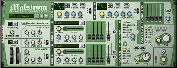
The following shows the Subtractor device, with the “Init Patch” loaded. The Init Patch is used as a starting point for building sounds. Note that the Init Patch does not start at ground zero, and instead is an actual patch that generates an actual sound. I find that in some circumstances you may want to start at ground zero. In this case, you can set all the sliders and knobs to their zero or center position and save the patch. This way, you can always load your new “Init Patch” anytime you like. I’m sure only the die hard sound creation gurus will go to this trouble, but if you are new to any synth, it’s always better to learn from the bottom up, than to have half a sound already generated for you. But that’s just my own opinion.
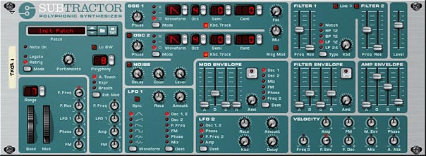
The Subtractor Synth Device
The Subtractor Synth Device. When the device is “Reset” from the context menu, the initialized patch is entered. This is used as a starting point from which you can build your sounds.

The Patches

Following are the various patch examples you will find within the patch pack, along with a brief description and key features of each. The idea behind these patches are to show you the versatility of the synth, and show some of the types of sounds it can produce. Of course, there are many more kinds of sounds. An oboe, bassoon, an ambulance siren, and the list can go on. I encourage you to try your own. But hopefully these can get you started and give you some ideas of how to work with the Subtractor.

  • Bass Example
  • Bass Wobble Example
  • TB303 Example 01
  • TB303 Example 02

These patches are probably the type of sound that is most commonly associated with the Subtractor: Bass. Octave separation between the two oscillators is key here, along with the right kind of filtering and amp envelope.

  • ChipTune Example

This type of sound is one that you’d find on any video game console from the ’80’s. The key to this kind of sound is use of the LFO set to square wave and modifying Oscillator Pitch. This creates the arp feel of the patch. In addition, the Band Pass Filter and setting the envelopes to a full decay and all other envelope parameters to zero gives the sound a minimal 8-bit feel. If you wanted to, you could use the Noise generator to add a little distortion to the sound. But it’s usually better to add a Scream FX unit set to “Digital” damage mode in order to recreate some “crunch” to the sound. Be sure to also keep the Oscillator waves simple as well. Remember, you’re trying to recreate very basic technology here.

  • Filter Sweep Example

This shows you how the Filter Envelope can be used to sweep the filter in your sounds.

  • Flute Example
  • Horn Example

These two patches show you how you can create some wind instruments. One of the keys to recreating these types of sounds is using the sawtooth oscillator and proper filtering. A little modulation helps as well. Generally, I find wind instruments use either Sawtooth or Sine waves, and benefit from a HP filter in Filter 1 and a then the Low Pass filter 2. Some tweaking with the envelopes and a little modulation affecting the pitch to give it a jump in pitch at the beginning can recreate the “blowing” sound that starts at the beginning of these sounds. As with everything in patch design, the devil is in the details.

  • FM Texture Example

Shows how using FM can give a whole new perspective to your sound, and can often generate interesting textures. FM, as well as Ring Mod can make the sound very unnatural, distorted, or even metallic. See the next “Glockenspiel” patch.

  • Glockenspiel Example

This is an example of a glock — or bell-like sound. The use of the Ring Mod feature is what really makes the sound here. The example presented is tonal, because the Oscillators are set one octave apart. But you can get some really interesting atonal bell sounds by separating the Octave in weird degrees (for example, try separating them by 6 or 9 semitones, or play around with odd “Cent” differences).

  • Guitar Example

Guitars are difficult — probably the most difficult — to reproduce. But if you can reproduce a piano sound with a synth, you can take an extra leap to try a Guitar sound as well. The two actually share some similar concepts I think. And while the Subtactor isn’t perfect for guitars, they are still do-able. I found that using Wave 15 in Oscillator 1 paired with a sawtooth provided the raw tones. Then a Bandpass filter 1 going to the Low Pass filter 2 seemed to work out well. I then set the Filter and Amp envelopes to similar values, with medium Decay and Release on both. Keep the Attack at zero to give that initial hard attack. The sustain is tricky, and you can leave it out if you want, or add just a little bit to keep the sound going. That’s your call. The other key to this sound is adding a little FM for a metallic sound. Then turn the Mix knob all the way left so that you’re only hearing the FM Carrier (Oscillator 1). That’s the basis for a typical Subtractor Guitar sound. But play around to see what type of sounds you can build from this technique.

  • Hi Hat Example
  • Kick Drum Example
  • Snare Drum Example
  • Tom Tom Example

These are some Drum examples. While all the drums are different and Subtractor is capable of producing a wide variety of drum sounds, there are some common characteristics. For example, most drum sounds don’t have any Sustain, and also have extremely short Attack — usually set to zero. There is minimal Decay and Release as well. So set up the Amp envelope with this in mind. In addition, your drums may or may not require pitching up or down, so you can disable the keyboard tracking for the Oscillators. Then use the Oscillator tuning to get them to sound accurate (usually in the lower register). This way, the drum will sound at the same pitch no matter where you play it on the keyboard. However, this may or may not be what you want.

Filtering is also important for drums. Generally, Bass, Snare, and Tom drums use Low Pass filtering. While Hi Hats, Crashes, Cymbals, and the like use Hi Pass filtering. The Noise generator can be very helpful here as well. For low Bass Drums, be sure to turn the Color knob closer or all the way left. This brings the register of the noise downward. For more of a biting drum, like a Snare, turn the Color knob closer or all the way to the right.

  • Mod Pad Example

Here’s an example of a Pad – a String Pad actually, which use two Sawtooth Oscillators (great for achieving nice string pad sounds). The idea behind creating a nice Pad sound, in my opinion, lies in two areas: A) The Amp Envelope settings, which are fairly slow. This means that the Attack, Decay, Sustain, and Release are generally pushed up quite high (over a value of 60 in most cases). And B) The modulations you create, which are usually slow as well. This can be anything from the LFO affecting the Mix or Amp, while the Mod Envelope affects the Phase of the Oscillators. The Rates for the LFOs should be set fairly slow (Rate knob more to the left) and the amount values should be subtle (more to the left) as well. This creates very soothing and meandering sounds which work well for Pads.

Of course, never forget that rules are meant to be broken, and nothing here is set in stone. I’m just presenting you with some generalities.

  • Morse Code Example
  • Noise Doppler Example
  • UFO Effect Example

These three show how you can create various special effects with the Subtractor. The Morse Code patch is a good example of how you can use the Random LFO 1 applied to the Filter Frequency in order to create a random Morse Code Sonar sound. Depending what Oscillator you are using and how it’s filtered, you can have it sound like a Telegraph, if you like. So give that a try.

The Noise Doppler Effect is a good example of how you can use the Noise generator on its own, without any Oscillators. The noise is modulated with the two LFOs to create a pseudo-doppler effect. Then the Mod Envelope is used to control Frequency Cutoff on the Low Pass Filter 2. And the Filter Envelope is affecting Filter 1. This all creates a double filter sweep that brings the sound in slowly as it’s sustained. Try playing a chord and note how the sound gets louder over time (as the filters are opened). The LFO 2 plays its part as well by cycling the Amp. A lot of mods working in tandem to affect a very simple Noise generator. Fun stuff!

And finally there is the UFO effect which showcases how you can create some interesting Alien-type sci-fi sounds. As with all the patches here — but moreso in this particular patch, try using the Mod Wheel to show some variation in the sound.

  • Organ Example 01
  • Organ Example 02
  • Piano Example 01
  • Piano Example 02

These four patches are examples of how to recreate organ and piano sounds using the Subtractor. I don’t know about you, but I find programming Pads, Pianos, Organs, and Basses are probably among the easiest types of instruments to reproduce with the Subtractor. I’m not going to go into all the details of how these patches are put together, because they all use different settings, Oscillators, Filters, etc. And you can take a look at them for yourself and then try your hand at creating similar kinds of sounds. I would say that a good starting point is a Sine wave and Low Pass filter though. Sometimes a Notch filter can work well. It all depends. So here are four examples.

  • PWM Lead Example

This shows how the Phase is used to offset and modulate the Oscillator wave, creating “Pulse Width Modulation” (or PWM for short). This is also referred to as “Phase Offset Modulation” (POM). Essentially, its the same thing.

  • Rhythmic Example

In this patch I tried to show how you can get some very complex rhythms using the two LFOs and the Mod Envelope together. The Mod envelope is applied to the pitch to create a sound that continually moves downward. LFO 1 is applied to the Filter 1 Frequency Cutoff to create a gate-like rhythm to the sound. And LFO 2 is applied to the Phase to create a PWM as Phase is swept back and forth. 2 things you can do: A) Try reversing the direction of the sound by inverting the Mod Envelope (click the upside down ADSR graphic button at the top right of the Mod Envelope section). B) Try adjusting the Rates of the LFOs. You can sync them to each other by keeping their rate values identical. You can separate their sync by using two different rates. It’s up to you. But this is different than syncing the LFOs to the tempo of the song; something else you can try out.

Tips for working with the Subtractor

Aside from the basic Oscillators, there are several other wave samples that are hard-coded into the device (represented by waves 5 through 32 in the Oscillator slots). Then there are the usual things that are familiar to most analog synths: 2 filters, 3 envelopes (Amp, Filter, and Mod), 2 LFOs, Noise generator, FM and Ring Modulation, Pitch Bend & Mod Wheels, and a very extensive Velocity parameter section. All of this should be familiar to the synthesist and sound designer, and I’m not going into all the ins and outs here. The Reason User Guide is an excellent resource which goes over most everything you will need to know in order to get familiar with the Subtractor.

What I do want to cover here are a few pointers that may not be obvious when using the Subtractor, or might cause some confusion when you begin to work with it. Think of this as some additional insight into the device which sooner or later you would figure out on your own. Maybe this might save you the trouble?

  • The Subtractor is monaural in two senses: It creates a single channel of sound, and can only generate one sound at one time. However, the device is polyphonic, in that you can play that same sound using multiple keys (think: chords). The number of keys that can be played at the same time is set up in the Polyphony setting (1-99). However, what you may not know is that some of the modulation is polyphonic as well. I know this sounds a little counter-intuitive, but here’s the deal: If you set up your patch to have a Polyphony setting above 2 (usually you want this higher at 8 or 12), then you can use LFO2 to affect the Oscillator 1 & 2 Pitch, Phase, Filter 2 Frequency Cutoff, or Amp. If you do this, playing a broken chord (one note after another) results in an LFO that retriggers separately for each note. This is different than the LFO 1 in the Subtractor, which is a global or monophonic LFO, meaning it does not retrigger with each new note.
  • Using the LFO 2 to affect the Amp is the way in which you set up Tremolo. It’s a shame that you can’t apply this Tremolo to the Mod Wheel inside a Subtractor patch (a fairly common Mod Wheel assignment), however, you can do this if you put the Subtractor inside a Combinator, and assign the Subtractor’s LFO 2 Amount to the Combinator’s Mod Wheel.
  • Those who are new to the Subtractor may not know that in order for FM or Ring Mod to function, you need to have both Oscillators enabled. This is because both of these features rely on the interaction between the two Oscillators. In addition, if you want to hear only the Frequency Modulated sound, without the Modulator, turn the Mix knob fully left. If you want to hear the Ring Mod sound without the Modulator, turn the Mix knob fully right.
  • The Noise generator is also similarly connected to the second Oscillator output, which means turning the Mix knob fully left while the Noise generator is on will reveal nothing from the Noise generator. To hear the Noise generator fully, turn the Mix knob fully right. Therefore, to get a mix between the Noise generator and an Oscillator, turn off Oscillator 2. Instead, set up Oscillator 1, turn on the Noise generator, and keep the Mix knob centered. If you instead want a pure noise sound, keep Oscillator 2 turned off, and turn the Mix knob fully right. This removes Oscillator 1 from the Mix and fully introduces the Noise generator.
  • And as with all rules of thumb, there are always exceptions. If you disable Oscillator 2 and enable the Noise generator, you can still use the FM knob to modulate Oscillator 1 with the Noise generator (remember that the Noise generator outputs where Oscillator 2 is output). You are effectively using the Noise generator as the second Oscillator, and this is used as the Modulator to Frequency Modulate Oscillator 1. So yes, there are exceptions. And while all of this may sound complicated, it’s really not. Think about it. Turn on Noise, increase FM, and turn the Mix knob all the way left. Then experiment with the various Oscillator 1 and Noise generator settings to see what you can come up with.
  • If your Oscillators are set to “o” as opposed to “-” and “x,” then the Phase knobs have no effect on the sound. Phase only works with subtractive (-) and multiplied (x) modes. You can, of course, set up mode combinations where Oscillator 1 is set to subtracive (-) and Oscillator 2 is set to “0.” In this case, only the Oscillator 1 Phase knob will have any impact on the sound.
  • The Velocity section can have an amazing impact on how the sound is played, and has a wide array of options. However, where a lot of new users get confused is in how to set up the Velocity knobs. First things first. Set up a matrix or Thor Step sequencer to play a single note repeatedly at a relatively slow speed, and create a velocity ramp up and down over the duration of the sequence (ramp the full range of the velocity). This sets up the sound to be played at the same pitch, with only the velocity changing as the notes are played. It also helps you to hear what’s going on with velocity. With that done, start experimenting with the 9 velocity knobs to hear how they interact and affect your sound.
  • Another thing to keep in mind when adjusting velocity parameters: When the knobs are dead center, velocity has no effect on the parameters. Turn the knob to the left and velocity has a negative impact on the parameter in question. Turn the knob to the right and the velocity has a positive impact on the parameter in question. In simple terms, if you adjust the Amp velocity in a positive way, the sound becomes louder the harder you play your keyboard (normally what you would expect). However, you can reverse this relationship by adjusting the amp velocity knob in a negative way, so that the sound becomes quieter the harder you play your keyboard.
  • And more about the velocity parameters: Note that if you have a parameter that is adjusted fully one way (for example, the Filter 1 Frequency slider is set to 127 or fully open), then adjust velocity to increase this parameter in the same direction (for example, the Filter Frequency velocity knob is adjusted in a positive direction), the velocity will have no impact on the sound. This is because the Filter Frequency is fully open, and can’t go any further. You could, however, adjust the Filter Frequency in a negative direction in this example, in order to close the filter the harder you play your keyboard.
  • Finally, one last note about the Phase Velocity parameter. Adjusting this will adjust both Oscillator Phase knobs in tandem by the same proportion. This means if you have one Phase knob set to 40 and another Phase knob set to 80, with the Phase Velocity knob set to 10 (positive), when you play the keyboard at full velocity, the Phase knobs will sound as if they are set to 50 and 90, respectively. You can, of course, set up one of the Oscillators to a mode of “o” as outlined earlier, so that the Phase of that Oscillator has no effect on the sound. Of course, this can change the sound. This tandem shifting of Phase is also true of the Phase knob that can be used as a destination for the Mod Wheel. So bear this in mind when adjusting these two parameters.
  • In case you were ever wondering, that second filter in Subtractor is a 12 dB Low Pass Filter, and it cannot be changed to any other Filter Type. Also, when working with it, turning it on will mean that the sound passes through Filter 1 and then into Filter 2 (Serially). With this setting, you can use the Frequency Cutoff sliders of both filters independently (and in some interesting ways — for example, setting up a High Pass Filter 1 and then having it go through the Low Pass Filter 2). Alternately, you can “Link” the Filters together. When they are linked, the Frequency Cutoff of Filter 1 controls the Cutoff of both filters (but the relative position of Filter 2’s Cutoff Slider is maintained). For example, if Filter 2 is set to 50, and Filter 1 is set to 80, moving the Filter 1 Cutoff Slider down to 70 will also reduce the Filter 2 Cutoff to 40. They work in tandem. Note: Low Cutoff Frequencies with High Resonance settings can produce severely loud sounds. This is amplified by the “Link” feature. As such, it’s always a good idea to A) Turn down the Resonance for both filters to zero before applying the “Link” button. And B) Turn down the volume if you are experimenting with the Resonance of either filter while the “Link” button is activated.
  • Filter 2 does have its own dedicated Filter Envelope. Use the Mod Envelope with a destination of “Freq 2.” Now you can control Filter 1 Frequency Cutoff with the Filter Envelope and Filter 2 Frequency Cutoff with the Mod Envelope, all at the same time. This allows you to create some pretty complex filtering in your patches.
  • Lo BW. Unless you are rockin’ out with your PII Pentium 200 Mhz computer from 1994, you will never need to enable this feature. Just pretend it’s not there.
  • Want a fatter sound? If both Oscillators are set to the exact same settings, detune them by a few centos in opposing directions (Oscillator 1 = -4 Cents / Oscillator 2 = +4 Cents). You’ll have to venture outside a simple Subtractor for other fattness tricks, but two of my favorites are A) creating a Unison device under the Subtractor (between the Subtractor and the Mix Channel). This automatically fattens your sound. B) After you have the Subtractor patch set up exactly as you want, duplicate the Subtractor and send both subtractors to separate Mix Channels. Then on the Mixer, pan Subtractor 1 fully left and Subtractor 2 fully right.

So that’s a little bit about the basics of the Subtractor synth, along with a new patch pack. I hope you’ve enjoyed it, and if you have any tips or ideas related to using the Subtractor, please share them. All my best, and happy sound designing!

 

78 – Creating Better Patches (Part 5)

In this fifth installment of my series on better patch design, I thought I would take a much-needed break from all the theory and synth jargon, and instead focus on some creative Thor synth ideas. I can almost hear the collective yawn after reading the last few articles. So let’s spice it up with a few videos that showcase some of the concepts we’ve talked about, but more importantly, let’s just have some fun fiddling around in Thor.

In this fifth installment of my series on better patch design, I thought I would take a much-needed break from all the theory and synth jargon, and instead focus on some creative Thor synth ideas. I can almost hear the collective yawn after reading the last few articles. So let’s spice it up with a few videos that showcase some of the concepts we’ve talked about, but more importantly, let’s just have some fun fiddling around in Thor.

You can download the project files here: better-patches-part5. This zip consists of a few Thor patches and demo .reason files that outline the ideas below. You can use any version of Reason above 4.0 (when the Thor synth was introduced to the world of Reason). Enjoy! Read on for more about these ideas.

The Hoover Sound (Redux)

Chris Petti did a great video on how to create a Hoover Sound in Reason using some Analog Oscillators and a Multi-Oscillator to fatten everything up. If you haven’t seen his video, I’m going to showcase it here. Have a look and build the patch first. We’ll use this as the base building block and figure out a few modifications you can add to enhance it’s flexibility. Here’s his video:

This patch is a really great sound as it is, and Mr. Petti does a bang up job of presenting it to us (not to mention his videos are way cooler than my own DIY camera work). Nonetheless, there’s lots you can do to add to his patch. So I’m going to start where Chris left off and see what we can do to make his patch more flexible, taking it to the next level of patch design. Check out the video below:

Button Trigger Madness

In my never-ending quest to solve interesting problems in Reason, I came across this dilemma. How can I use the button in Thor as a toggle switch to step through the Thor Sequencer? I wasn’t happy with the “it’s not possible” answer. So here’s what I devised. It’s actually a nice simple solution which allows you to use the Thor button as a cycler. The power in this trick is that when the Sequencer is set to “Step” mode, the button can be used to cycle through all 16 steps. If you watch the video below, you’ll see how this can help you devise Thor patches that contain 16 distinct sounds within a single Thor patch.

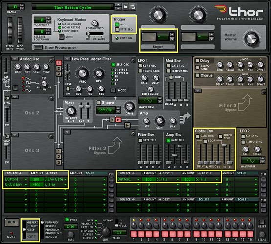
Here’s the short version of how you set it up (see the Chiptune video below for a practical application):

  1. Open a new Reason document. Go into Edit > Preferences, and on the “Audio Tab,” ensure the Sample Rate is set to 44,100 (should be the default). Then close out of this dialog.
  2. Create an initialized Thor device.
  3. Turn off the “Step Sequencer” green light in the Global section’s “Trigger” area. While we’re doing that, label Button 1 the “Stepper.”
  4. Turn off the Global Envelope’s “Gate Trig” green light.
  5. Turn up the Global Envelope’s Sustain to full (0.0 dB), and turn down all other Global Envelope parameters to zero.
  6. In the Modulation Bus Routing Section (MBRS), create the following two lines on the left side:

    Button1 : 100 > G.Env Gate

    Global Env : -100 > S. Trig

  7. Now, enter the following in the MBRS on the first line on the right side

    Button1 : 100 > S. Trig : 100 > S. Trig

  8. In the Step Sequencer section, change the Run Mode to “Step.”
The Thor Button Cycler, showing all the changes that need to be made to the Thor init patch

Now when you press button 1, you’ll notice that the Step sequencer moves forward one step when turned on, and another step when turned off. In essence, we’ve tricked Thor into thinking that both button “on” and button “off” should trigger the Step Sequencer to “Run.” The Global Envelope was required because it is always left on, and so can be manipulated without requiring a Midi Note to “gate” the envelope.

You can now use the Step Sequencer’s Note, Curve 1, Curve 2, Gate Length, etc. to control any aspect of the Thor patch that you like, and build up different sounds at each step of the Step Sequencer. Think of generating 16 different Bass tones or 16 different Pads, Strings, Drum sounds, or any interesting sounds you can dream up. The only limitation is that you won’t have access to the Global Envelope — a minor limitation given the fact that you can get Thor to generate 16 different sounds from a single patch.

Chiptune Sounds (Redux)

As I was experimenting one day, I stumbled upon. . .

. . . a wonderful way to create some Chiptune sounds using the Wavetable Oscillator in Thor and affect it’s “Frequency (FM)” parameter with a stepped LFO. Sometimes it’s not how crazy you can make things. Instead, it’s about keeping things ultra simple. Have a look at the video to see how I paired this Chiptune idea with the above “Button Trigger Madness” idea to create 4 different Chiptune sounds within a single Thor patch.

Here’s the video:

Creating a Sweep

This is an interesting patch that will show you an alternate use for the Velocity performance of the Patch. Since the sweep changes the Volume (along with a few other parameters) over time to sweep the sound upward to full volume, you probably don’t want to have Volume modulated by Velocity. Instead, you can use the Velocity information from the musician’s performance to adjust the speed or rate of the sweep, making it rise slowly when the keys are played softly, and faster when the keys are played harder. You could also set up a button to reverse the Velocity behavior, if you like (see my previous tutorials in this series for explanations on how this is done).

Here’s the video:

Using the FSB for Practice

Another idea I had was to take patches from one synth and transfer them over to another synth within Reason. In this video, I’ll show you how you can take one of my favorite Subtractor patches and recreate the sounds inside Thor. While not every sound from the Subtractor (or Malstrom, for that matter) can be accurately reflected in Thor — they are, for the most part, different synthesis algorithms and techniques underlying each synth — you can still get pretty close, depending on the patch you start out with. It’s good mental exercise. It will help you get to know all the synth parameters and how they work. And you have an endless array of sounds at your fingertips in the FSB.

So why not give this a try with your favorite sounds? And there’s also another reason to transfer patches from the Subtractor into Thor: At the end of the transfer, you’ll still have the Rotaries, Buttons, and step sequencer to enhance or expand on the patches — something the Subtractor lacks. So here’s the video to show you the method I used:


So that’s part five in the series. As always if you have any questions or want to contribute your thoughts and ideas, I encourage you to do so. I’m always interested in hearing new ways you’ve found to work with Reason. All my best until next time.

70 – ChipTune Sounds

There’s a wealth of great information out there on recreating the sounds of old computer chips, like the Commodore 64 or old SID chips and video console chips, and using these sounds to create tunes (Chiptune). I honestly knew very little about the subject until I, along with several other very talented folks, were asked to put together some fresh new sounds for the Reason 6 Factory Sound Bank (FSB). So here I’m going to explore and explain how I created a few of these sounds, and show you that you can definitely recreate some convincing Chiptune sounds using nothing but Reason and a little experimentation.

There’s a wealth of great information out there on recreating the sounds of old computer chips, like the Commodore 64 or old SID chips and video console chips, and using these sounds to create tunes (Chiptune). I honestly knew very little about the subject until I, along with several other very talented folks, were asked to put together some fresh new sounds for the Reason 6 Factory Sound Bank (FSB). So here I’m going to explore and explain how I created a few of these sounds, and show you that you can definitely recreate some convincing Chiptune sounds using nothing but Reason and a little experimentation.

There are no additional project files for this tutorial because all the project files can already be found in the FSB (Factory Sound Bank) for Reason 6. So read the article, watch the videos, and I’ll point to where you can find these chiptune sounds and show you how they are put together.

The Process: It’s all in seeking out the Answers!

Before I delve into creating these wily little playful sounds, I want to shed a little light on how I approached the subject. Because hopefully that might give some insight into the process of sound creation and more importantly, might inspire you to seek out the knowledge you need to tackle any sound design project, even if you know very little about it. The whole process starts by asking yourself two questions:

  1. What is the sound I’m looking for? What does Chiptune sound like?
  2. How can I recreate those sounds inside Reason.

The answer to the second question depends upon the first, so your first step is to seek out Chiptune sounds. Try to find some sites on the internet that cater to that specific sound and immerse yourself in them. It also helps if you can download a few sounds in your genre of choice and then deconstruct them using a spectrum analyzer. The more you do this, the better you will be at instantly recognizing what type of Oscillator was used, envelope settings, and the like. And yes, this is another plea for the Props to introduce a fully-featured Spectrum Analyzer in Reason. Because, for a sound designer, this is a very important analysis tool.

Once you have an idea of how the genre or specific instruments sound, the next step is to seek out information on how those sounds are built. I went to my best virtual friend next to Google to get the answer: Wikipedia. Enter “Chiptune” into the search box, and you have all the information you need to figure out how to build chiptune sounds inside Reason (or at least a very good start). Look for keywords like which “Oscillators” and “Waves” and “Filters” were used. Then you can transfer this knowledge over to Reason and be well on your way to creating vintage Chiptune sounds.

So if you really want to know about Chiptune, go here: http://en.wikipedia.org/wiki/Chiptune. After you’ve read that (especially the section on “Technology” and “Style”), come back here and we’ll continue with taking the knowledge from that article and build our chiptune sounds in Reason.

Note: There are several sites dedicated to creating Chiptune sounds, software and hardware used to create chiptune sounds, discussion groups, sound share sites, and a plethora of everything to try to recreate these old video game consoles and chips. Simply searching on Google will give you a wide variety of information and I urge you to explore those avenues as well, if this is your thing.

Components of Chiptune Sounds

Now that we have an idea of what Chiptune sounds like, and we know a little about what elements of the synthesizers are used to recreate those sounds, we can jump into Reason. Of course since this is a Reason article and since we’re using Reason software, it makes perfect sense that we are taking the software route to recreate these sounds. But that doesn’t mean you can’t recreate them via hardware instead. You could also, if you’re lucky, have access to those older chips from the 80’s and build your own box if you are feeling inspired by your inner engineer spirit. There’s also a wide variety of other software dedicated to recreating these chips and chip sounds. But that’s a whole other article for a totally different kind of blog. Here, it’s all about software and Reason.

Most of the components of the chiptune sounds use some or all of the features below, and are very simple to create in Reason. As a matter of fact, you can use any or all of Reason’s synths to mimic some very realistic chiptune sounds. Where the fun comes is adding your own variation or style to the sound. Since the chips used to create the sounds of the 80’s arcade devices were very basic, they required very little CPU and that holds true even today. So you can create whole songs out of them with very little strain on your processor.

  • Usage of Square Wave (also called Pulse Wave)
  • Usage of the Bandpass filter
  • Bitcrushing to add distortion and a low quality feel
  • White noise for drum sounds
  • Arpeggios were simulated with a fast-changing pitch (something easily simulated by an LFO affecting the Pitch)

That’s pretty much it in a nutshell. Now let’s see how we can set up our sounds using all three Reason synths.

Malstrom Chiptune Sounds

Here’s the video that shows you how to build some chiptune sounds using the Malstrom. Think of this as your own Malstrom chiptune emulator:

Here’s the process to create some interesting Chiptune sounds with the Malstrom (the short version):

  1. Create a Combinator and a 14:2 Mixer inside the Combinator. Then create a Malstrom, so it is auto-routed to the first channel of the Mixer.
  2. Turn off filters A & B in the Malstrom.
  3. Select Curve 26 for Modulator A, and Curve 3 (square wave) for Modulator B. You can play around with the Curves after you’ve created most of the patch. The key is to select sharp-edged (stepped or square) waves. This provides a distinctive chip sound for the patch.
  4. Turn the Rate knob for Modulator A to around 104, and the Rate knob for Modulator B to around 96. Also set the “Modulator A to Pitch” knob to 63 (all the way up). And then set the “Modulator B to Motion” knob to around 22
  5. In Oscillator A, select “VSWaves” and turn the Motion down to -64. Then turn the Index up to 127. Finally, set the ADSR envelope of Oscillator A to 0 / 127 / 0 / 0
  6. Set Polyphony to 1.

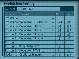
Now when you play the Malstrom you should hear some interesting chippy sounds coming out of it. You can now set up the Combinator Rotaries/Buttons to play around with the Rates of both Modulator A & B, as well as the Modulator A to Pitch, Modulator B to Motion, and Oscillator A Index. Here are the settings I entered for the Malstrom Emulator patch I created for the Reason 6 FSB. The idea is to keep things playful, flexible and usable.

The Combinator's Modulation Routing settings for the Malstrom, which were used in the Chiptune Emulator A patch from the Reason 6 FSB

Adding some “Crunch” or Bitcrushing into the Mix

To add a bit of bitcrushing to the sound, you can do the following:

  1. Select the 14:2 Mixer and create a Scream 4 device. This will auto-route to the first Auxiliary of the Mixer.
  2. Turn the “Return” knob of Aux 1 down to around 50 or so. Then turn Channel 1 Aux 1 all the way up to 127.
  3. Select the Scream device, and set the Damage Control to full (127), Damage Type to “Digital,” and P1 to 105.
  4. Select the “Scream 4” in the Combinator Mod Routing section, and enter the following settings: Rotary 4 > Parameter 2 : 0 / 127. Also set Button 4 > Damage On/Off : 0 / 1.

This way, Button 4 acts as the Bitcrush On/Off switch, and Rotary 4 acts as a “tone” knob for the bitcrusher. If the effect is too much for you, reduce the Return knob on the Mixer for Aux 1 down a bit more. If it’s not enough, turn it up.

Thor Chiptune Sounds

Here’s the video that shows you how to build some chiptune sounds using the Thor synth. Think of this as your own  Thor chiptune emulator:

Here’s the process to create some interesting Chiptune sounds with Thor (the short version):

  1. Create a Combinator and a 14:2 Mixer inside the Combinator. Then create a Thor synth, so it is auto-routed to the first channel of the Mixer.
  2. Ensure Oscillator 1 is Analog (by default, this should already be set). Then change the wave to a square (pulse) wave. Use the Oscillator 1 Mod setting to 64.
  3. Bypass the Filter 1 slot, but ensure the Oscillator is still going into Filter 1 (the red “1” button to the left of the Filter 1 slot).
  4. Set the LFO 2 to a square (pulse) wave, and the Rate to somewhere around 11.3 Hz. Things are more interesting if you don’t “sync” the LFO to the tempo, so leave that off for now.
  5. Set the Amp Envelope’s ADSR to 0 / 127 / 0 / 0
  6. Set Polyphony to “1” and Release Polyphony to 0 (zero).
  7. In the Modulation Bus Routing Section (MBRS) at the bottom of Thor, enter the following: LFO2 : 66 > Osc1 Pitch
  8. Setting up the “Bitcrusher” is exactly the same as previously described when creating the Malstrom patch, so you can set that up for your Thor chiptune emulator if you desire.

Now when you play the Thor synth you should hear a classic Chiptune sound. The next step is to set up the Combinator Rotaries/Buttons to play around with the Rate of the LFO2, as well as the PWM (Pulse Width Modulation) of Oscillator 1.

The interesting thing about using Thor is that you also have access to the built in step sequencer. So another approach is to set up a random pattern to a “Pendulum” setting, then unsyncing the step sequencer, and having it trigger from a button on the Combinator (see the video for more on this). Setting up the sequencer this way means that you have an “auto-sequenced” pattern triggered from the Combinator button. Handy for instant chiptune.

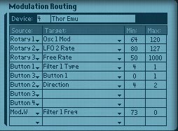
Here are my own Combinator settings for the Thor device:

The Combinator Modulation Routing settings for the Thor chiptune Emulator.

Now let’s have a look at some Chiptune sounds triggered via Kong.

Here is another little patch that I put together for the FSB, along with some other talented people who helped out by providing a few of their sounds as well. It’s a little Kong Kit that you can experiment with. Note that in order to create some of the drum sounds that are classic 80’s arcade, you will want to use “white noise.” This formed the basis for classic chiptune drums.

So there are a few outlines to create classic 80’s arcade sounds. With a little tweaking, I’m sure you can come up with several authentic sounding video game sounds using Reason. And I’d sure love to hear them. Furthermore, armed with this knowledge, why don’t you try out using the Subtractor to create chiptune sounds. And if you come up with some good ones, please be sure to send them my way and let me have a listen. Until next time, happy Reasoning.

29 – Synth Drums from Scratch

The subject of today’s tutorial is how to create your own standard drum sounds via synthesis. Here, I’m going to show you a few techniques to bring these drums to life, with little more than a Thor, Malstrom, or Subtractor synth, and some supporting modules. This is a great alternative to using Drum samples or relying on sample CDs for your drum sounds, though those are both great alternatives that should not be overlooked.

Often times we don’t have access to a real drum kit and it’s not feasible to get real true-to-life drum samples to use in your own work. Or you may just want the sound of a synthetic drum as opposed to the real thing. One option is to purchase some sample CDs. Another is to create your own drum sounds from scratch, using the synths provided in Reason. That’s the subject of today’s tutorial. Here, I’m going to show you a few techniques to bring some standard drums to life, with little more than a Thor, Malstrom, or Subtractor synth, and some supporting modules.

I should start by saying that with the addition of Kong in Reason 5, creating drums has never been easier. Load up a physical drum or a synth drum module and you’re more than halfway there. However, for those that don’t have Reason 5 yet, then this tutorial is for you. Everything below is created using the Reason 4 devices. This goes to show you that you don’t necessarily need Kong to create interesting drum sounds. So let’s get started.

You can download the project files here: Synth Drums from Scratch. This is a zip file that contains 3 Combinators and 1 Thor patch outlining the different drum sounds from the tutorials below. The Combinator parameters will affect the sound of each drum. I’ve tried to tailor them so that you can get a very wide variety of drum sounds out of each Combinator. Have fun with the various buttons and rotaries to get the sound you want out of them.

The Bass Drum

The first drum we’ll emulate is a Kick or Bass drum. This is probably one of the easier drums to emulate because it has that very bassy deep and punchy feel to it. The hardest part about programming this kind of drum I think is in the Compression, which most every Kick drum should have. How it is compressed is really a matter of taste, but getting just the right sound you want is probably going to rely on the way you compress it. A close second in terms of seasoning your Bass Drum is using EQ to accentuate the correct frequency or frequencies. Here’s how I would go about creating a Kick Drum using Thor.

The Tom Drum

The second drum type we’ll create is a Tom Tom drum. This time, I’ll use a Malstrom with a TubeSlap Oscillator to emulate it. This oscillator is great for sounds like these, and can produce just the formant sound that is needed with a typical Tom drum. Of course, you can emulate all of these different drums using any of the synths. This is just one way to recreate the sound. You could instead, try using a Thor oscillator with a Formant filter to get the Tom Drum sound you’re after. Be sure to explore more on your own to find the sounds that truly inspire you.

The Snare Drum

The third type of drum I’ll recreate is a Snare drum. For this, I’ll use a subtractor with two Oscillators and a Bandpass filter. Then we’ll use a Noise Oscillator in Thor to add that extra tail that a Snare drum can have. To wrap it all up, we’ll combine them both and set up a little programming to the rotaries in order to get a little more out of our Snare sounds. Using these parameters we can create a variety of Snares, instead of a single type of sound. See how it’s done:

The Hi Hat

Finally, there is the tried and true Hi Hat sound, both open and closed. To emulate this one, we’ll use a Thor FM pair and Noise oscillator going through two State Variable filters set to High Pass and Notch mode in Thor. I’ll emulate the open and closed Hi Hat and tie it to a Thor button. This way, you can access both the closed and open state of the drum with the click of a button (and from within the same Thor synth, which makes it very CPU friendly). Of course, if you want to separate them, you can duplicate the Thor device and use one Thor for the “Open” Hi Hat position and one Thor for the “Closed” Hi Hat position. It’s all up to you and very flexible.

So there you have it. Four basic drums created with the three different synths in Reason 4. If you have any other drum sounds that you would like to contribute or tips for drum creation, please feel free to share with us. Until next time, have fun working your own magic in Reason and Record!

28 – Weird Sci-Fi Synth Sounds

Here are a few ways you can create some trippy and out-there sounds using the synths in Reason. I’ve had a lot of requests for these kinds of sound creations, so I thought I would throw a few ideas out there. These sounds provide you with three different patch ideas for three different Sci-Fi type sounds. Enjoy!

Here are a few ways you can create some trippy and out-there sounds using the synths in Reason. I’ve had a lot of requests for these kinds of sound creations, so I thought I would throw a few ideas out there.

Sure. This time around I’ll provide the patches found in this project here: weird-sci-fi-patches The file contains 2 Thor patches with 2 variations on the Sci-Fi sound, a Malstrom with an Alien voice, and a Subtractor ominous spacey patch. Enjoy!

First off, here’s an idea which uses the Noise Oscillator and a Multi-Oscillator to create some really weird sounds in Thor. The key features here are the use of the Bipulse Shaper and the Self-Oscillating filters. In this example, they are probably even a little more important than the actual Oscillators that you’re using. So here’s the video:


The second kind of other-worldly sound is brought to you by the Malstrom. In this case, I tried to create an Alien from outer space voice using the Electronik voice and the Jews Harp grains inside the Malstrom. As you’ll see, the Malstrom is exceptional for these kinds of crazy effects. You can have a field day tweaking knobs on here. The main focus should be on utilizing the Pitch knob, as well as all the other knobs to affect the Oscillators. In this way, you can mangle your audio beyond any human recognition. Makes for exactly what we need to build our Alien Voice. Here’s the video:

Now of course we shouldn’t forget the Subtractor in our quest to create some freaky sound effects. So let’s try giving it a whirl. This time I’m going to go for a more Ominous space sound, almost a Pad-like sound. This seems like it would be great as an intro for a huge and ominous scene and reminds me of when the Borg attacked the Enterprise in the feature-length movie: “Star Trek: First Contact.” Yes, I know. Major geek right? Well, anyway, this uses some FM for the deep bassy sound, and a low Octave Oscillator. From there, you just need to adjust the filter. One other interesting thing you could do is sweep the filter frequency from Closed to open and back again. The key of course is to experiment, experiment, and experiment some more!

So there you have it. A few different Sci-Fi sounds for you to jump into. There’s billions more sounds just waiting to be created. If these help as a starting off point for you, then great. Glad I could help. And if you have any comments, suggestions, tips or tricks, please let me know. It’s from your requests that I end up making these tutorials in the first place. So keep the requests coming. And Happy Reasoning!

21 – Massive Combi Drum Kit

Turn a Combinator into a 61-synth drum kit that spans the range of the Matrix pattern sequencer so you can use the Matrix to trigger your drum hits. Yes it’s massive. Yes it’s crazy. And yes, you should try it out! Why? Because apart from being time consuming, it’s dead easy to accomplish. And it doesn’t have to break the CPU bank.

This project was a real blast to put together. Essentially it involves turning a Combinator into a 61-synth drum kit that spans the range of the Matrix pattern sequencer so you can use the Matrix to trigger your drum hits. Yes it’s massive. Yes it’s crazy. And yes, you should try it out! Why? Because apart from being time consuming, it’s dead easy to accomplish. And it doesn’t have to break the CPU bank.

Download the project file here: minimal-super-kit. This zip file contains my Minimal Super Drum Kit Combinator with 61 synth sounds that can be played by the Matrix. I’ve added 32 random patterns in the Matrix which is assigned to a Rotary knob so you can dial in a pattern you like. Also, you can turn the matrix off using button 1, so that you can play the drum kit with your keyboard controller if you wish. This is a great flexible way to show off your drum kit creation chops. So enjoy! And when you’ve had it with my own drum sounds, try your hand at creating your own. Read on to find out how.

There’s also a few extra devices in the Combinator, and assignments on the other Rotaries / Buttons which affect the drums globally. Feel free to explore their routings as well if you’re interested. The focus here, however, is turning your Combinator into a massive drum kit which can be sequenced using the Matrix.

Back to Basics: Setting things up

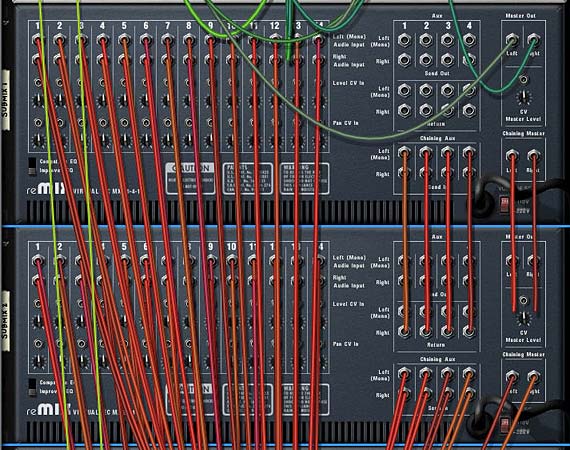
  1. Open up a new document with a 14:2 Mixer and then create a new Combinator. Inside the combinator, create five 14:2 mixers all in succession so that they are all chained one after the other.

    The five 14:2 Mixers are chained together.
    The five 14:2 Mixers are chained together.
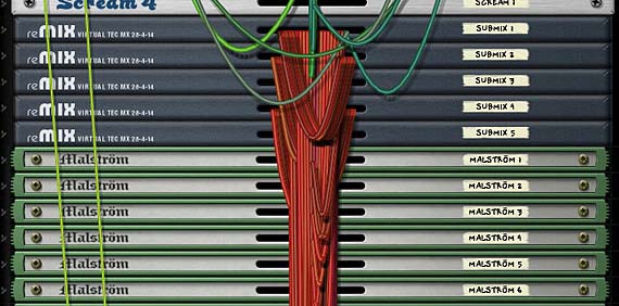
  2. Create 61 Synths. Yes, that’s right. 61 Synths. These can be any combination of Thors, Malstroms, or Subtractors. one trick before you go nuts copying and pasting is to create one instance of Thor, one Subtractor, and one Malstrom, and then initialize all 3. This way, only one oscillator or graintable is used and it will be light on the CPU. Once you’ve done that, copy and paste so you have 61 different synths and connect them each to their own mixer channel.

    Each of the synths are connected to their own Mixer channel.
    Each of the synths are connected to their own Mixer channel.
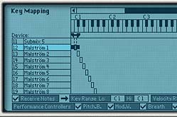
  3. Now this is the trickiest part of the whole tutorial. Click the “Show programmer” button on the front of the Combinator, and select the first synth in the list at the top. Notice in the Key Mapping area on the left part of the Combinator screen, the key range for this synth spans the entire keyboard range. If you look at the bottom of the Key Mapping area, the value under Key Range is C-2 (Lo) to G8 (Hi). We’re going to change these values so that both read C1. The easiest way to do this is to click and drag upward over the “Key Range Lo” field until it reads “C1.” Once you’ve done that, you can click and drag down all the way on the “Key Range Hi” field. This means that the synth will only be triggered by pressing C1 on your keyboard controller.
  4. The first Synth selected in Key Mapping. See that the range listed is C1 (Lo) to C1 (Hi)
    The first Synth selected in Key Mapping. See that the range listed is C1 (Lo) to C1 (Hi)
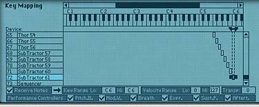
  5. Sweet! Now do this for each subsequent synth, but incrementing each one by one note value upward on the scale. So, for example, the next synth is only triggered by C#1 and the one following that by D1, and so on up the scale until you have the last synth in place at C6. Ta da! Now each synth can only be triggered and played from it’s corresponding note on the keyboard controller. And taken as a whole, the entire kit ranges the same 5-octave span of the Matrix (from C1 to C6).
  6. The last Synth selected in Key Mapping. See that the range listed is C6 (Lo) to C6 (Hi).
    The last Synth selected in Key Mapping. See that the range listed is C6 (Lo) to C6 (Hi).
  7. Now comes the really fun (but tedious) part. Go through each synth one at a time and sculpt your drum sounds. Go wild. Enter some amazing Kicks, Snares, Toms, Hi Hats, Rim shots, glitch mayhem, or whatever sounds you really enjoy listening to through Reason. Don’t be shy. Jump in and have some fun. And if you’re really hard pressed for some ideas, sift through the Factory Soundbank (FSB) for some inspiration. There are plenty of synth ideas in there.
  8. Note: audition your sounds using your keyboard controller. This way you can hear each note triggering each synth. If you forget your place on the keyboard, minimize your entire stack of synths by holding down Alt as you press on the minimize arrow of one of the devices. This will automatically minimize all devices within the Combinator. Now press a key on your controller and look for the “Note On” light as you press. This “Note On” light will show you which synth is triggered by the note you are playing. Since each synth is tied to an individual note on the keyboard, only a single “Note On” light will flash when you press a single key. Trust me, this is a great time saver when working with so many devices.

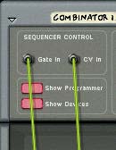
  9. Add a Matrix under everything, flip the rack around, and tie the “Note/Gate CV out” cables from the back of thedevice into the Sequencer Control “Note/Gate CV in” on the Combinator. Flip back around to the front again and start dialing in some Note/Gate patterns into the Matrix pattern banks. Or use the right-click context menu to select some random patterns for the various Matrix pattern banks.

    Connecting CV cables from the Matrix to the Combinator's Sequencer  Control section.
    Connecting CV cables from the Matrix to the Combi's Sequencer Control section.
  10. Finally, go back to the Combinator’s Modulation Routing section and with the Matrix device selected, enter the following settings:

Rotary 1 > Pattern Select: 0 / 31 (assuming you’ve entered patterns in all 32 pattern banks of the Matrix)

Button 1 > Pattern Enable: 0 / 1

Entering the Matrix Sequencer Parameters in the Combi's Modulation Routing Section.

Keeping Button 1 off means that you can play the Combinator in a “live” situation, accessing the drums to be played in real time and ignoring the Matrix. Turning on Button 1 automates the drums and plays the drums according to what is programmed in the Matrix. Spinning the Rotary 1 knob will select from the 32 Matrix pattern banks. You can also automate pattern changes for the Matrix in the Sequencer if you create a sequencer track for the Matrix.

I hope you’ve enjoyed this little exploration of what can be done with a bunch of synths and a Matrix inside a Combinator. You can create some gigantic kits using this technique. And it can be an alternative to using the NN-XT for a sample-based drum kit.

As with any method, there are pros and cons to this approach. I like it because it can be much easier to tweak the sounds later if you want to adjust any of the synth parameters for your various hits. Personally, I feel this can give you more flexibility than storing your kit in an NN-XT. That being said, the downside is that it’s not quite as compact, takes some time to load up in your song, and it’s not sample-based so it’s not as “organic” as samples in an NN-XT can be. Both approaches, however, are valid. It all depends what you’re after.

If you have any other ideas or unique ways in which you’ve created your own kits please share them with us. I’d love to know some new techniques that I may not have thought about before.

Until next time, I hope this inspires you to build some kick-ass drum kits. Good luck!

17 – Auto-Panning Methods

Learn a few different ways to automatically pan your audio back and forth from left to right or right to left in the stereo field using the LFOs of the Reason synth devices or a Matrix pattern device. As you’ll see, these methods are not that difficult to understand or implement.

Here I’m going to go over a few different ways you can automatically pan your audio back and forth in the Stereo field. As you’ll see, the methods are not that difficult to understand or implement. Once you have this process down, you can also go on to do more complicated panning techniques, such as combining waveforms for panning, panning filter frequencies, or panning your EQ to create left to right frequency sweeps. Of course, I’m not going to go into all of these advanced techniques. Rather, I’ll delve into the world of auto-panning slowly to get your mind wrapped around some of the different methods you can use in Reason and Record.

Download the project files here: auto-panning-methods. This is a single .rns file with 4 different Auto-Panning Combinators set up for you. Each one affects the same audio source and then gets sent to their own mixer channels in the 14:2 mixer. Mute/solo the channel you want to hear to listen to the examples. Note that each Combinator in this set uses a different way to pan the signal. Each has their strengths and weaknesses, as you’ll see in the tutorial below.

At it’s heart, panning simply moves your sound from Left to Right or Right to Left in the stereo field. In order for the software to pan your sound, you must set up something that signals the audio to move from one side to the other. Usually, this means assigning an LFO or Mod Envelope to control the pan position of your audio. Since Reason and Record have CV inputs assigned to every channel in their mixers, as well as directly on the Mix and Audio Devices themselves, panning any audio source can be achieved with one simple CV connection. Also note that you can pan a mono signal from one side to the other just as you can pan a stereo signal from one side to the other.

Setting up a simple Pan using the Subtractor LFO1

Here is one of the easiest ways to create your automatic panning using the LFO of a Subtractor device:

  1. Open up your audio source in Record or Reason. This can be any synth device, audio channel, mix channel, etc. The point is that you need an audio source to affect.
  2. Next, create a Combinator. Then inside the Combinator, hold your Shift key down and create a 6:2 line mixer and a Subtractor.
  3. Initialize the Subtractor. This means reducing all the values in the Subtractor to zero (range/polyphony/ADSR envelopes, etc.).
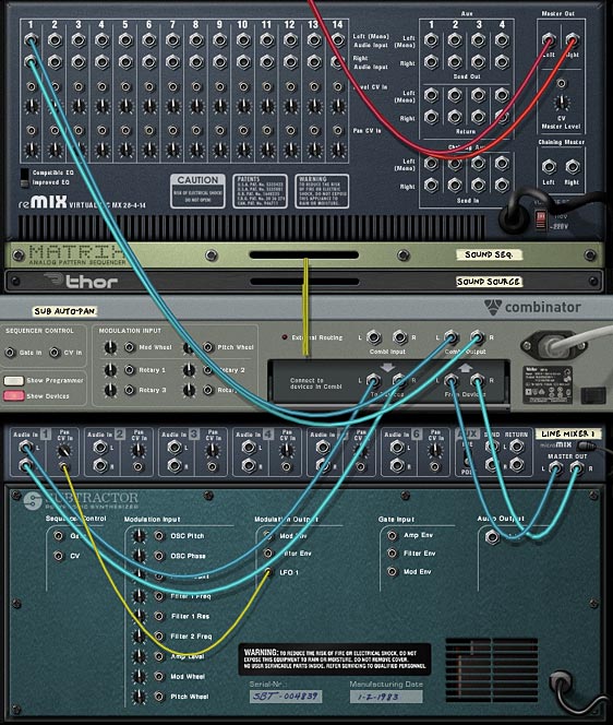
  4. Press the “Tab” key to flip the rack around to the back. Connect the Combinator’s Left and Right “To Devices” to the Mixer’s first channel’s Left and Right inputs. It’s not shown in the image below, but you’ll have to also route the audio source Left and Right output to the Left and Right Combinator input.
  5. Connect the LFO1 CV out from the Subtractor’s Modulation Output section into the Pan CV in on the mixer’s first channel. Then turn the trim knob all the way right. This means that the CV will fully control the panning of the audio source.
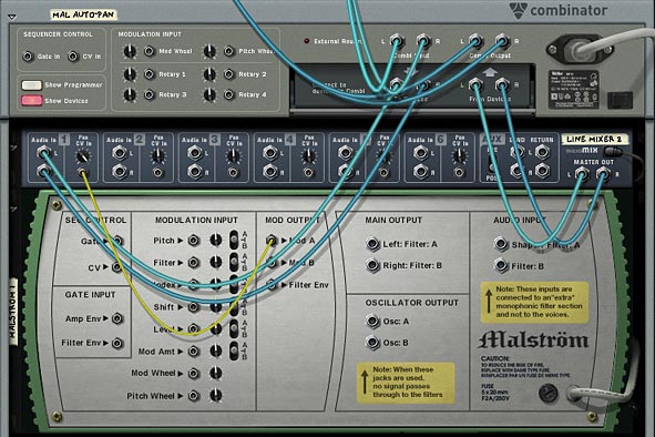
The back of the rack showing the Subtractor LFO1 modulating the Pan of the Sound Source.

With this setup, the subtractor’s LFO1 is controlling the audio position in the stereo field. This is a great setup, however, there are two main problems: 1. You have access to a very limited set of LFO waveforms (6 to be exact), and none of those waveforms is a straightforward “sine” wave. And 2. Since the Subtractor is free-running, there’s no way for you to turn off the LFO. It will continually pan from side to side, with the Panning speed based on the Rate in the LFO1 section. I can live with #1, however, #2 is a huge hindrance and is enough for me to say no thanks! Let’s find a better way.

Panning with the Malstrom Curves (a step upward)

Now let’s up the game a little.

  1. Delete the Subtractor we just created, and instead hold the shift key and create a Malstrom device. Again, initialize the device by moving all the faders to zero and reducing the polyphony to 1 and the pitch range value to zero. Turn everything off except for the “Modulation A Curve” — leave that little light on.

    The fully initialized Malstrom
    The fully initialized Malstrom
  2. Flip to the back of the rack, and route a CV cable from the Mod A output to the Pan CV in on the line mixer.

    The back of the rack showing how Mod A is controlling the Pan CV in on Mixer Channel 1
    The back of the rack showing how Mod A is controlling the Pan CV in on Mixer Channel 1

Now the Curve from Mod A is controlling the Panning for the sound source. The nice thing about this setup is that you can turn Mod A on or off, which in turn turns the panning on or off (unlike previously in our Subtractor example). Furthermore, there’s another added benefit: you can select from the Malstrom’s 32 different waveforms. Now that’s some serious power.

Panning with Thor (an alternative)

The Malstrom is great if you want to play with a lot of curves to pan your sound source. However, there are a few advantages to using Thor’s LFO2 instead.

For a detailed run-through of how to setup Thor to auto-pan your sound source, have a look at the video below:

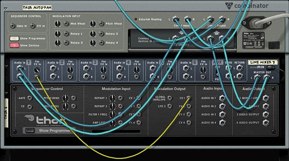
In this situation, you would delete the Malstrom, and initialize a Thor in its place. Send the CV1 Output to the Pan CV in on channel one of the line mixer. Then in Thor’s mod matrix, you use LFO2 as a source and CV1 Out as a destination. Finally, you could set up a button on the Combinator so that when the button was off, Thor’s “Mod Destination Amount” is set to zero (0), and when turned on, it is set to 100. This way, the button acts as a switch to turn the CV on/off. Just have a look in the project files to see how this is set up.

Thor CV1 out going to the Pan CV in on the first mixer channel.
Thor CV1 out going to the Pan CV in on the first mixer channel. Thor's LFO2 being sent to the CV Out1 (in turn routed to the Pan CV in on the mixer)

The benefit to using Thor is that you can assign the LFO2 delay and Key Sync parameters to the Combinator Rotaries/Buttons, which is something you can’t do with the other methods. So it all boils down to how you want to pan your sound. There’s no better or worse way to do it. If you know the panning won’t ever need to be turned off for the duration of your song, you can use the Subtractor. If you need control over the delay and Key Sync parameters of the LFO, then you know Thor is the only choice.

The Matrix (a wild card)

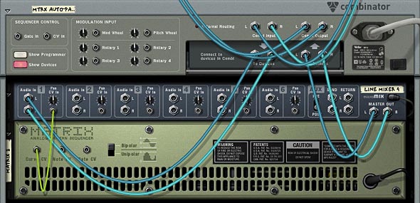
The last way I’m going to discuss is how you can use a Matrix to create your own waveform to affect the panning of a sound source. This is just like the previous methods, except you draw in a pattern inside the matrix, and on the back you connect the Curve CV to the Pan CV input on the first channel of the line mixer. Be sure to change the front panel of the matrix to “Curve” and on the back, select “Bipolar” as the curve selection. Panning is a bipolar process going from -64 to +63 with zero (0) being dead center. So the matrix needs to utilize this bipolar functionality to have the panning work correctly.

The Matrix Curve CV being sent to the Pan CV input on channel 1 of the mixer
The Matrix Curve CV being sent to the Pan CV input on channel 1 of the mixer The Matrix from the front with a Curve setup.

The drawback is that the curves are always in sync with the tempo (which may or may not be what you want), and your rate selection is limited to locked-in resolutions in the matrix. You can’t have any concept of a free-running rate system with this setup. On the plus side, you can draw in up to 32 unique patterns (on each of the matrix pattern banks), and then assign a rotary to the pattern selection to cycle through the different programmed curve patterns.

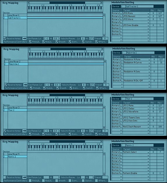
Now, I’ll show you how the Modulation Matrix is set up on each of the Combinators. Looking at these setups, you can see how each one has a different set of parameters that can be controlled. This is how you determine what the right “fit” is for your sound source. Get to know these inside out and it will become really easy to figure out which one works best for each of your audio scenarios:

From top to bottom: Sub, Mal, Thor, Matrix auto-panner Combinator setups.

So there you have it. A few different ways you can auto-pan your sound source. Things can get pretty interesting if you start crossing pans or inverting one sound source with another, so that when one sound is in the left channel, another sound is in the right channel (hint: use the spider’s “inverted” split to output one CV split to the second channel). You also don’t have to use an LFO to achieve your panning. You can easily draw in automation for the panning knob on the mixer channels and have full control over drawing in the panning curves yourself in the sequencer. Oh there’s lots of possibilities.

So do you have any suggestions or other interesting ways you’ve developed for panning your elements in Reason and Record. I’m always looking for innovative ways to use panning in my mixes. It’s a great way to add some movement and modulation to your pieces. Move up the rate fast enough and you almost have a vibrato or phased effect on your sound, which can add interest. So tell me what you’ve come up with and share it with all of us.

Here’s a bonus little rns file for Sterioevo (see his comment below). He was suggesting using an RPG-8 as a Panning device. Now the problem with this is that the Arp is not bipolar. The notes / gate CV output from the Arp is unipolar. So with a little tweaking, you can create something that comes close. A kind of pseudo-panner using the Arp. This was a pretty interesting technique so I thought I would provide the file here: arp-auto-panner-idea Enjoy!

Selig also had a comment on the Propellerhead forum that is important when talking about panning your audio. I thought I would quote him here, as it’s a very good point:

“The main problem I always had with using the CV Pan input is that the panning only goes half way to either side – I want a panner that goes ALL THE WAY!!! And the easy way to accomplish that is to route the LFO’s CV output (from any synth) to a combinator Rotary Knob’s rear input (cranking the little knob up all the way) and assign it to the mixer’s Panner with the combi’s Programmer. Check it out – NOW you have some serious P – A – N – N – I – N – G ! And all your cool tips will still apply. :-)”

5 – Create a Grain Sampler

Learn how to create your own homemade grain sampler. This allows you to take a single sample, and affect the playback, sample start position, Repeat length, Grain Length, and Filter Frequency, among other things.

If you’ve ever used the Malstrom in your projects, you’ll undoubtedly see the benefit of grain synthesis. It’s like sound design under a microscope, as you can take a very short piece of sound and chop it up into little bits and start/stop the playback where you like. The fact that you can’t add your own grains into the Malstrom is somewhat disconcerting, but there’s a simple way you can create your own grain sampler, where you can add any sound and use that sound as a grain. This can be very effective in adding some new creative spark to your musical projects. And it opens you up to adding any sound you like and deconstructing it as you see fit. So let’s see how we can do this.

The files used for this project can be downloaded here: grain-samplers. It includes 4 Combinators that are set to play a clip of random notes on the sequencer. To try each one out, you’ll have to mute all the other Combinators via the Main mixer channel. I’m sure this is self-evident, but it never hurts to explain it here. As always, this is open source so feel free to use it in your own projects. Just please provide a link back here or a credit or kudos of some kind. After all, I do this for free. 🙂

Creating the Basic Grain Sampler

  1. Start by creating a Combinator, and in the Combinator create an NN19, Subtractor, and Matrix in that order. 
  2. The NN19 is what we will use to contain the sample or “Grain Table.” This is our sound generating device. So starting there, initialize the device so we have a base from which to start. Bring the Polyphony down to “1,” and set the Spread Mode to “jump.” Finally, change the Pitch Bend  Range to “0.” Don’t worry, I’ll explain why we made all these settings after we’ve set everything up.
  3. Load up your favorite sample into the NN19. You only need one. Alternately, you can wait until the end of the setup to load your favorite sample. If you load the sample at the end of this procedure you can then test out the various samples and play around with them at will using the Combinator rotaries that are going to be setup in just a minute. But for now, just have something loaded so you hear some sounds.
  4. Moving to the Subtractor, bring the polyphony down to “1,” and change the Pitch Bend Range to “0.” More importantly, change the Mod Envelope settings to the following: A=0, D=0, S=127, R=0.
  5. On the Matrix, change the number of steps to “1,” and raise the gate to 127 on the first step.
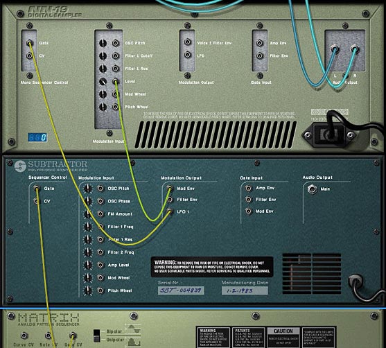
  6. Turning to the back of the rack, there’s really very little to cable. First, cable a CV connection between the “Mod Env”  in the Modulation Ouptut section of the Subtractor to the Level input on the NN19. Also, raise the pot next to this input to 127. Second, cable a CV connection from the LFO1 on the Subtractor to the Gate input on the NN19. Third, cable a CV connection from the Gate CV on the Matrix to the Subtractor’s Sequencer Control Gate input.
  7. The basic cabling for our Grain Sampler
    The basic cabling for our Grain Sampler
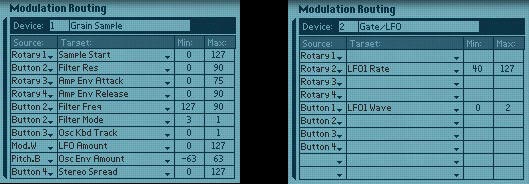
  8. Now comes the fun part: Programming the Combinator. Flip the rack around to the front and show the Combi’s programmer. Here are the settings that we have to make:

For the NN19 (Grain Sampler):

Rotary 1 > Sample Start: 0 / 127

Rotary 3 > Amp Env Attack: 0 / 75

Rotary 4 > Amp Env Release: 0 / 90

Button 2 > Filter Res: 0 / 90

Button 2 > Filter Freq: 127 / 90

Button 2 > Filter Mode: 3 / 1

Button 3 > Osc Kbd Track: 0 / 1

Button 4 > Stereo Spread: 0 / 127

Pitch.B > Osc Env Amount: -63 / 63

Mod.W > LFO Amount: 0 / 127

For the Subtractor (LFO):

Rotary 2 > LFO1 Rate: 40 / 127

Button 1 > LFO1 Wave: 0 / 2

The modulation for the NN19 Sampler (Left) and the Subtractor (Right)

Here is an example of the various things you can do with a basic grain sample:
[ti_audio media=”277″ repeat=”1″]

Explanation of the Functionality

Now for some explanation. The NN19 acts as the grain sampler and the heart of everything. This is why it’s so heavily programmed. The amplitude is controlled by the Subtractor because we set up the Mod Envelope’s Sustain to 127, and cabled the cv from the mod envelope to the level input. And the mod envelope of the subtractor remains “on” because we are sending a gate signal from the matrix. This is simple and effective, and makes our grain sampler very “light weight” by only containing 3 devices.

But don’t let this simple setup fool you. The way we programmed everything gives you a very wide degree of control over the sound — and that sound can be any sample you choose to load into the NN19. Let’s take a peek at what’s going on at the front of the Combinator.

Pitch Wheel: This is set to control the oscillator envelope amount from the NN19.  This is probably one of the coolest and freakiest uses of the Pitch Wheel you could have, and is great for mangling sounds into weird and wonderful effects. 

Mod Wheel: This is set to control the LFO amount on the NN19, for more strangeness, giving the sound a warped and warbled effect.

Rotary 1: Controls the Grain Index, much like the Malstrom’s “Index” function operates. What this is doing is controlling the start position of the sample on the NN19

Rotary 2: This controls the rate of the LFO from the Subtractor, or the speed of the grain playback. All the way left and you get a very slow speed, but turn up the knob and it can get extremely fast.

Rotary 3: Controls the Amp Envelope Attack of the NN19. All the way left gives you fast attack, and all the way right gives you a slow attack.

Rotary 4: Controls the Amp Envelope Release of the NN19. All the way left gives you a short release, and all the way right gives you a long release.

As for the buttons, they are all set up to provide some further sound morphing capabilities.

Button 1:  Switches the LFO Type on the Subtractor. You can program this button to switch between any 2 of the 6 LFOs available on the Subtractor, depending which ones you like best.

Button 2: Controls the Filter mode of the NN19. When off, it uses the default LP12 settings, with a fully open frequency and no resonance. Turn it on, and it turns into a HP filter with the frequency somewhat open, and the resonance dialed up high.

Button 3: This is a very important button in my estimation. It controls the Keyboard Tracking of the Grain Sampler’s Oscillator. This is going to largely depend on how you want the notes in your sequencer to be played by the Grain Sampler. If you look at the project files included here, you’ll see I placed a bunch of random 1/32 notes in a clip on the sequencer. The notes are all different pitches between C2 and C4. If you leave the Key Track button off, the pitch of the notes do not affect the sound. The sound remains constant. If you turn the Key Track button on, then the pitch of the sequencer notes affect the Grain Sampler’s oscillator, and have an affect on the pitch heard. To me, this gives you a great deal of control over how you play your sequencer clips. All with a simple switch.

Button 4: This controls the Stereo Spread of the Sample playback. With this button turned off, there is no spread. With it turned on, full spread is applied across the entire stereo field. Also, since “jump” was selected on the NN19’s Spread mode, it will jump back in a random fashion between the left and right fields.

Exploring Alternate Grain Sampler Ideas

Now that we have the basic grain sampler idea laid out, there’s a few variation Combinators that are included in the project file which you can explore in greater detail. I’ll lay out some of the highlights here.

Mal Grain Sampler: This Combinator inserts a Malstrom and uses it’s “A Curve” in place of the Subtractor’s LFO. It’s then tied to the Rotary 3 on the Combi, so you can use any one of the 31 Curves to affect the gate of the Grain Sampler. The “B Curve” is also plotted to the Oscillator Pitch on the Grain Sampler, and is also plotted to the Rotary 3 on the Combinator. Button 1 on the Combinator turns the B Curve on or off. This means that when you press button 1, it creates all kinds of weird sound morphing (or pitch morphing) to the sample, based on the position of the Rotary 3 knob.

Thor Grain Sampler: This Combinator uses the Thor’s LFO in place of the Subtractor. This isn’t that big of a deal or much of a change. But what’s nice about the Thor is that you can map the Thor’s Sequencer Curve 1 to affect the Oscillator Pitch of the Grain Sampler. Turning on Button 1 on the Combinator starts Thor’s sequencer to Run and provides some Pitch shifting to the sample. The added benefit of using the Thor is that you’re not limited to using the Global parameters. Since the Thor Gate is always on, you should be able to utilize any of the Thor parameters to affect your sample sound. You just need to program them in the Modulation Bus Routing System (MBRS).

Triple Thor Grain Sampler: This Combinator layers 3 Grain Samplers together, all playing different samples. The curves on the 3 Thor’s are all different, and the Mode of the step sequencers in them are set to play randomly. This creates a lot of pitch variation when you press button 1 on the Combinator. Instead of Rotary 3 and 4 affecting the Attack and Decay of the Grain Samplers, I set them to control the level of Sample B and C respectively through a line mixer at the top of the Combi stack. This way, the sample you add into the “Sample A” NN19 is always playing at full level, while Sample B and C’s levels can be adjusted (I didn’t want to give up the functionality on either of the first two rotaries, so that’s why Sample A is always at full level. However, you can create a sequencer track for the Line mixer and adjust the level via automation in the sequencer if you like). Try adjusting the programmer settings on the first two rotaries if you want to have the various samplers playing at differing speeds and at different index points. This can create some pretty elaborate sound designs.

As a final tip, you can try automating the Rotaries for any of the Combinators to randomize things. I would also suggest you read a great article by Lewis72 on the art of Granular Synthesis on his blog. He also created a very nice grain sampler which you can download for free. If you find any other ideas out there on the web on the art of Grain Sampling within Reason and Record, please feel free to post them here in a comment. And if you find these useful or create something interesting with them, please let me know. I’d love to hear how you can use these in your own work. All my best!