12 – Crossfading Mals & Filters

Since Ed’s Thor Shaper article, I’ve been thinking about how to use this information in real-world examples. One idea is to crossfade the Grain Samples in the Malstrom and another idea is to crossfade all 4 Thor filters to affect one sound source. Lots of fun!

Since Ed’s Thor Shaper article, I’ve been thinking about how to use this information in real-world examples. One thought came from a post I saw on the Props forum. Basically, the issue was that you can’t assign the Malstrom Grains to a Combinator Rotary to effectively switch between the 80+ Grain Samples. It’s pretty easy to assign and switch between Modulator waveforms using a Rotary, but not the actual samples in the Malstrom. So this got me thinking of how you could go about switching between these Samples. And truth be told, there’s probably some really obscure way to do it which uses Thor and some heavy CV connections. But here is something that might just inspire you and be the next best thing.

You can download the project zip file here: crossfading-malstroms-and-filters. This file contains 2 rns files with the Combinator setups explained below. One is a 16-Malstrom crossfader, and the other is a 4-way Thor filter crossfader. I would recommend you download them and open them up as you read. It will make things a little easier that way.

Crossfading 16 Malstrom Grain Samples

In this setup, I’m using 16 Malstrom devices and each device is sent to a Mixer Channel in two 14:2 Mixers. The CV from the various Thors are sent to the Mixer Levels, where the level trim knobs are pushed all the way right, and the Mixer channel Levels are set to zero. If you haven’t already seen Ed’s interesting and enlightening tutorial on the subject, you should read it here: Ed’s Thor Shaper Tutorial. It goes through using the Sine Wave Shaper in Thor to create a 4-way Crossfader. In this way, you can cross-fade between 4 different Malstroms. Each Malstrom’s Oscillator A is set to a different Sample.

Since you have 4 Rotaries, each Rotary is set to 4 Malstrom devices. Giving you a total of 16 different Oscillators. Also, since one or more oscillators will be playing at any one given time, I’ve set up each button on the Combinator to mute the specific series of Oscillators. Button/Rotary 1 affects the first group of 4 (Malstroms 1-4), Button/Rotary 2 affects the second group of 4 (Malstroms 5-8), and so on. Only 10 Malstroms should be applied to a single Mixer because you can only map 10 parameters from any one device to the Combinator, and you need all 10 channel mutes mapped to the various Combinator buttons.

To take this a step further, you could create 6 Combinators, which together would contain the full 82 Oscillator Samples used by the Malstrom. Then you could crossfade between any oscillator you like. The sweet spots for each of the rotaries are as follows:

0 = Oscillator 1 Full Level

42 = Oscillator 2 Full Level

85 = Oscillator 3 Full Level

127 = Oscillator 4 Full Level

Any integer between those values will provide a crossfade between the two Oscillators on either side of the value. This can be seen as a downside or an upside. If you want a pure switch between Oscillator 2 and 4 for example, you can automate the Rotary to go straight from 40 to 85 in your sequencer using a Rotary automation lane. In this sense, you can use the Rotary as a 4-way button switcher between each Oscillator.

On the downside, you couldn’t effectively crossfade between Oscillator 2 and Oscillator 6 (on Rotary 2) the way the current Combinator is set up. But if you Reorganize the way the buttons mute, you could effectively do this. I’m open to anyone who has any other suggestions on how this could be achieved. Another downside is that since a different Malstrom is used for each Oscillator, you’ll have to tweak the settings on each Malstrom to get exactly the sound you want. If you want to keep everything consistent between all Malstroms, you’ll have to do it through automation (the easiest way I think). Simply automate one parameter on the first Malstrom in the sequencer, and copy that automation clip into every other Malstrom’s automation lane. It’s a bit of a pain, but it will keep all Malstroms in line, if that’s what you want.

On the upside, since there are 16 different Malstroms, you can fine tune the sound of each of them separately. If you have all the mutes off, you can effectively crossfade between 4-8 Malstrom sounds/devices at once just by shifting the Rotaries around. This adds some very interesting Sound Layering potential.

As it stands, the first 16 Oscillators from the Malstrom are applied to the 4 Rotaries on the Combinator. As I said, you could build up a stack of 6 Combinators to include all the Malstrom Oscillators. In this way you can build up various sounds and switch between the various Oscillators. Does this help anyone out?

Crossfading all 4 Thor Filters, and then some. . .

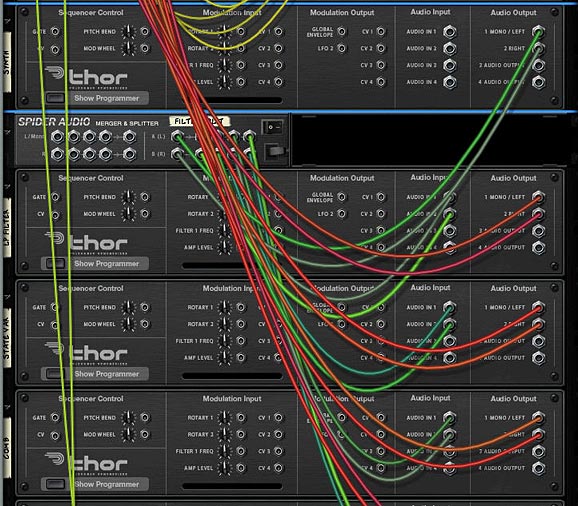
Next, let’s take a look at how we can crossfade all of Thor’s filters to affect one synth sound. In this case, it’s fairly simple to set up. First, create a Combinator, and set up Ed’s 3 Sine Shaper Thor’s to handle the CV like the previous example (along with a 14:2 Mixer). Then create a Thor and load up a synth sound. Start off with something simple so that you can really hear the different filters affecting the sound. Then create a Spider Audio CV Merger / Splitter, and send the synth’s Left and Right Audio Outputs to the splitter’s inputs. Create 4 Thors underneath the splitter and send each of the 4 splits to these respective Thor’s Audio Inputs 1 and 2. Finally, send the 4 Thor’s Left and Right Audio Outputs to the first four 14:2 Mixer channels.
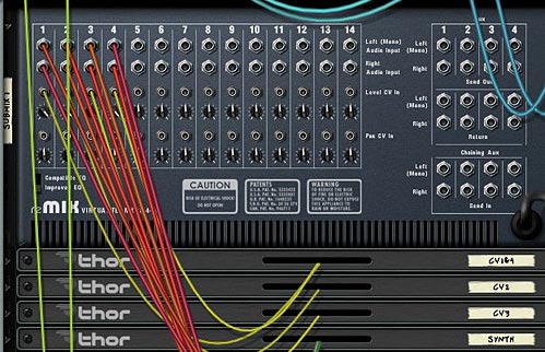
The setup with The Sine Shaper CV and Audio outputs from Thor into the Mixer
The Thor Synth Audio being split and sent through the 4 Thor Filters

On the front of the Rack, add a Low Pass Ladder Filter in the first Thor’s Filter 3 Slot. The settings for this filter are shown in the image below. In addition, add the following into the Modulation Bus Routing System (MBRS):

Audio In1: 100 > Filt3 L.In

Audio In2: 100 > Filt3 R.In
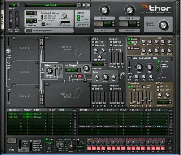
The Low Pass Ladder Thor Filter settings on the front Panel

Enter the same settings in the other 3 Thors, but with different filters, so you have the State Variable filter in Thor 2, Comb filter in Thor 3, and Formant filter in Thor 4. While you’re at it, play around with the Global ADSR envelope so that it sounds to your liking for the 4 different filters. It’s ok if these settings are different for each filter. This will just make your sound more interesting. One thing I kept the same across all 4 Thor Filters is the FX section (Delay and Chorus). This way, when the filters are transitioned, the FX remain similar across the board.

Now let’s turn to our Combinator section and do some serious routings in the Mod Matrix. Here’s the settings you will need for each of the Thor Filters (they are the same for all 4, but must be applied to all 4):

Rotary 1 is reserved for the Filter Crossfade, so I’m not going to go over it here. You can see it in the Project File rns.

Rotary 2 > Filter 3 Freq: 0 / 127

Rotary 3 > Filter 3 Res: 0 / 127

Rotary 4 > Filter 3 Global Env Amount: 0 / 127

Button 1 > Delay On: 0 / 1

Button 2 > Delay Sync: 0 / 1

Button 3 > Chorus On: 0 / 1

Button 4 > Filter 3 Global Env Invert: 0 / 1

Mod.W > Filter 3 Drive: 50 / 127

The Combinator Mod Bus Routing settings for each of the Filters

Now, what’s happening is that the Mod Wheel controls the drive amount on each of the Filters, While Rotary 1 cross-fades all the filters. This is the main Rotary, and it has the same sweet spots as the previous Malstrom patch. Rotary 2 and 3 control the Frequency and Resonance of the filters, and Rotary 4 adjusts the Envelope of the filter. Button 4 inverts this envelope. The remaining buttons are left for the Delay, Delay Sync and Chorus. Since all the parameters are the same for all the filters, they all shift together. This can be a positive or a negative. You can’t individually set the filters, but at least they sound pretty good when transitioned. Depending on your ADSR settings for the Global Filter, the Envelope Rotary and Envelope Inversion Button may be different for each filter. But as I said before, this can add some nice variety to the sound.

Use this Combinator as a template for your own sounds. All you have to do is add your own patch into the Thor “Synth” or change the Thor “Synth” to any other Synth or Sampler device if you like. Then you’re in filter crossfading heaven.

A huge thanks to Ed for being the inspiration for these patches. Please let me know what you think and if you can think of any other applications that this crossfading technique can have, by all means share it with us. Until next time, have fun with these.

Ed’s Thor Shaper Tutorial

I’m always amazed with EditEd4TV’s ability to analyze what should be a simple signal path. He literally blows my mind when it comes to this technical stuff. And I find myself reading it about 5 times before some part of it actually sinks in. And of course the real fun comes in figuring out just “what” musically you can do with this information. So not to disappoint, Ed is back with a great tutorial on the inner workings of Thor’s Shaper feature, and more specifically the “Sine” wave inside the shaper. If you feel brave enough, my young paduan learners, then venture forward where quite honestly no man has gone before. . .

I’m always amazed with EditEd4TV’s ability to analyze what should be a simple signal path. He literally blows my mind when it comes to this technical stuff. And I find myself reading it about 5 times before some part of it actually sinks in. And of course the real fun comes in figuring out just “what” musically you can do with this information. So not to disappoint, Ed is back with a great tutorial on the inner workings of Thor’s Shaper feature, and more specifically the “Sine” wave inside the shaper. If you feel brave enough, my young paduan learners, then venture forward where quite honestly no man has gone before. . .

Download the project files here: EditEd4TV_ThorShaperFiles. They contain an Excel spreadsheet with the settings for various sine wave values/positions, as well as Ed’s 4 source cross-fader which was designed using the Shaper’s Sine wave. Quite a brilliant design idea.


Thor’s Shaper can produce a number of interesting distortion effects when processing an audio signal from any of the three oscillator slots, but one of the more arcane features of the shaper is the processing of CV data. In this setup I’m routing the mod wheel data, 0-127, into Filter 1, which is in bypass mode (no filter), which is then routed into the Shaper, set in the sine wave preset. So that you don’t bypass the learning here, I’m not providing the patch, as it’s better to get your hands dirty and learn the hard way, so let’s make this specific patch before moving on:

Processing CV data through Thor’s Shaper

  1. First, create a Thor device and initialize the preset if necessary.
  2. Next, set filter slot 1 to bypass.
  3. Deactivate oscillator 1 routing to filter 1, and activate it for filter 2.
  4. Activate the routing button to send filter 2 to the amp (it’s directly below the Shaper’s Drive knob).
  5. At this point, if you set the Step Sequencer to Repeat mode, and press the Run button, you should hear a basic repeating pulse coming from oscillator 1. If you don’t hear this, go back and check your settings before moving forward.
  6. Next, in the Step Sequencer, move the Steps knob on the far right so that we have only 1 step. For this single step, set the gate length from 75% to 100%. At this point, if you press the Run button you should hear a single pulse that drops in volume. Change the oscillator type from sawtooth to a sine wave for a more pleasant tone, and raise the amp envelope sustain level from -21.8 dB (default) to full 0.0 dB. At this point you should hear a steady sine wave tone. Again, if you don’t hear this, go back and check your settings before moving forward.
  7. In the Modulation Bus Routing Section, make the following assignment:

    Source -> Amount -> Destination -> Amount -> Scale

    Mod Wheel -> 100 -> Oscillator 1 pitch

  8. At this stage, if you raise the mod wheel you should hear the pitch rise and fall as you move the mod wheel – this is direct control with essentially linear control/results. Change this amount value to 0 for the time being.
  9. Now activate the Shaper, change the mode to Sine, and in the Modulation Bus Routing Section, make the following assignments:

    Source -> Amount -> Destination -> Amount -> Scale

    Mod Wheel -> 100 -> Filter 1 Audio Input

    Shaper -> 100 -> Oscillator 1 pitch

  10. At this stage, if you raise the mod wheel you should hear the pitch first rise, but then suddenly begin to fall. This is the sine wave of the Shaper controlling oscillator pitch. At the default of 37, you’re hearing just a portion of what’s available in this shaper setting. For a nearly perfect full sine wave cycle, set the Shaper Drive value to 50. If you listen carefully to the results, you’ll hear that with the Mod Wheel at full 127, the pitch is slightly higher than with the Mod Wheel at 0. To verify that things are off a bit, create an Analog Oscillator in oscillator slot 2, set the type to sine wave, and engage the routing button to filter 2 for oscillator 2. With the Mod Wheel at 0, you’ll hear the two oscillators in perfect sync, but with the Mod Wheel at 127, they’re off a bit. To trim this, in the Modulation Bus Routing Section, modify the previous assignment to this:

    Source -> Amount -> Destination -> Amount -> Scale

    Mod Wheel -> 100 -> Filter 1 Audio Input -> 2 -> Rotary 2

  11. You should hear Oscillator 1 pitch drop a bit. Now turn up Rotary 2 and you’ll hear the pitch rise to meet up with Oscillator 2, which is unaffected by the Mod Wheel. A Rotary 2 setting of 62 is nearly perfect. Sweep the Mod Wheel from 0 to 127 and you should hear the full sine wave cycle, landing nearly perfectly with both oscillators showing the match.

Through painstaking research, I went through and found the settings for various sine wave values/positions. You can view the chart in the Project Files download (above).

To plot out a sine wave in Excel, the magic number we’re working with is 20.21267. The A column serves as our Mod Wheel range. In the B column we find the result of a formula which works with the Mod Wheel values and multiples of the magic 20.21267 value.

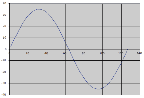
When you open the spreadsheet you’re seeing the 1/4 cycle output in the chart:

the 1/4 cycle Sine wave output

Copy the E5 to I5 range and paste into the E22 to I22 range and you’ll see the result in the chart:

a nearly perfect cycle of a sine wave

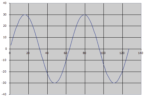
It’s a nearly perfect cycle of a sine wave. To chart out two full cycles, copy and paste E9 to I9:

Charting out 2 cycles of a Sine wave

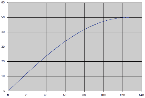
One thing to keep in mind here is that the CV output limits change as you raise the Drive value. At a 1/4 sine wave setting (Drive value at 0 and a scale value of 34 with Rotary 2 at 0), the Shaper will output a CV value of +50 (it’s not entering the negative range of the bipolar output). At the 4 sine wave settings (Drive value at 91 and a scale value of 2 with Rotary 2 at 4) the Shaper will output a CV vale of +/- 29. The spreadsheet changes all of this for you, and adjusts the chart accordingly.

Viewing the CV value in Thor

  1. To view the CV value in Thor, let’s first make sure we’re seeing true +/-127 values from the Mod Wheel, so place this Thor inside a Combinator, and in Thor’s Modulation Bus Routing Section, make the following assignment:

    Source -> Amount -> Destination -> Amount -> Scale

    Mod Wheel -> 100 -> CV Out 1

  2. Now route CV 1 output on the back of Thor to the Combinator’s Rotary 1 input. In the Combinator’s Modulation Routing Section, make the following assignments:

    Source -> Target -> Min -> Max

    Rotary 1 -> Mod 12 Destination Amount -> -100 -> +100

    Rotary 1 -> Mod 13 Destination Amount -> -27 -> +27

  3. Change Combinator knob 1 from 63 to 64. This visualization isn’t perfect, but it’s fairly close. Raise the mod wheel and note the two amount values in Thor’s Modulation Bus Routing Section rising with the mod wheel. At full throw, they should add up to 127, and at 0 it’s approximately 0 (you may see negative values). Now modify the previous assignment to this:

    Source -> Amount -> Destination -> Amount -> Scale

    Shaper -> 100 -> CV Out 1

  4. Raise the Mod Wheel and you’ll find the values range from approximately +34 down to -36. This is basically a range of 70, so we can essentially call this +/- 35.

So… what is all this good for? What are the applications? I don’t know yet, but it does potentially open up a lot of possibilities for those folks out there with creative and curious minds. One design is a 4 source cross-fader, which is included in the Project files (download above). The Combinator is within a Reason file for maximum compatibility with everyone out there.

Inside this Combinator you’ll notice that the Shaper Driver values for “CV2” and “CV3” Thor units are set for 42, which to my ears extended the fade out time for the mixer faders to a better sounding value. The “CV2” and “CV3” Thor units are identical, except via the Combinator Modulation Routing section, CV3 Thor’s Mod Wheel values are inverted, so the full throw is 0, and the lowest position is 127. This is essentially allowing you to send that sine wave backwards (not upside down) via the Combinator knob. I know, that’s confusing a bit, but sit and stare at your screen for a few hours and it might make sense – it took a while to figure it out, and now it makes sense to me, but it wasn’t easy at first. These Thor units send bipolar CV data to raise and lower the mixer volume levels. When the values go into the negative, those CV values are of no use to the mixer, thus the channels remain at 0 volume. The other Thor, “CV1 and CV4” is sending out linear CV values as opposed to sine wave shaped values – these are being offset via a DC offset value from the two Step Sequencer CV values, one for each CV output. To add a bit of crossfade between 1&2 and between 3&4, adjust Rotary 1 on the “CV1 and CV4” Thor.

Well, that’s about it – hope this is mind-bending for you all.


Ed “EditEd4TV” Bauman

• NOW AVAILABLE ‘Reasonable Help 2010: http://baumanproductions.com/reasonablehelp.html
• Facebook: http://www.facebook.com/pages/EditEd4TV/46599212364
• Reason Files: http://www.baumanproductions.com/reason.html
• Tunes: http://www.soundclick.com/EditEd4TV