78 – Creating Better Patches (Part 5)

In this fifth installment of my series on better patch design, I thought I would take a much-needed break from all the theory and synth jargon, and instead focus on some creative Thor synth ideas. I can almost hear the collective yawn after reading the last few articles. So let’s spice it up with a few videos that showcase some of the concepts we’ve talked about, but more importantly, let’s just have some fun fiddling around in Thor.

In this fifth installment of my series on better patch design, I thought I would take a much-needed break from all the theory and synth jargon, and instead focus on some creative Thor synth ideas. I can almost hear the collective yawn after reading the last few articles. So let’s spice it up with a few videos that showcase some of the concepts we’ve talked about, but more importantly, let’s just have some fun fiddling around in Thor.

You can download the project files here: better-patches-part5. This zip consists of a few Thor patches and demo .reason files that outline the ideas below. You can use any version of Reason above 4.0 (when the Thor synth was introduced to the world of Reason). Enjoy! Read on for more about these ideas.

The Hoover Sound (Redux)

Chris Petti did a great video on how to create a Hoover Sound in Reason using some Analog Oscillators and a Multi-Oscillator to fatten everything up. If you haven’t seen his video, I’m going to showcase it here. Have a look and build the patch first. We’ll use this as the base building block and figure out a few modifications you can add to enhance it’s flexibility. Here’s his video:

This patch is a really great sound as it is, and Mr. Petti does a bang up job of presenting it to us (not to mention his videos are way cooler than my own DIY camera work). Nonetheless, there’s lots you can do to add to his patch. So I’m going to start where Chris left off and see what we can do to make his patch more flexible, taking it to the next level of patch design. Check out the video below:

Button Trigger Madness

In my never-ending quest to solve interesting problems in Reason, I came across this dilemma. How can I use the button in Thor as a toggle switch to step through the Thor Sequencer? I wasn’t happy with the “it’s not possible” answer. So here’s what I devised. It’s actually a nice simple solution which allows you to use the Thor button as a cycler. The power in this trick is that when the Sequencer is set to “Step” mode, the button can be used to cycle through all 16 steps. If you watch the video below, you’ll see how this can help you devise Thor patches that contain 16 distinct sounds within a single Thor patch.

Here’s the short version of how you set it up (see the Chiptune video below for a practical application):

  1. Open a new Reason document. Go into Edit > Preferences, and on the “Audio Tab,” ensure the Sample Rate is set to 44,100 (should be the default). Then close out of this dialog.
  2. Create an initialized Thor device.
  3. Turn off the “Step Sequencer” green light in the Global section’s “Trigger” area. While we’re doing that, label Button 1 the “Stepper.”
  4. Turn off the Global Envelope’s “Gate Trig” green light.
  5. Turn up the Global Envelope’s Sustain to full (0.0 dB), and turn down all other Global Envelope parameters to zero.
  6. In the Modulation Bus Routing Section (MBRS), create the following two lines on the left side:

    Button1 : 100 > G.Env Gate

    Global Env : -100 > S. Trig

  7. Now, enter the following in the MBRS on the first line on the right side

    Button1 : 100 > S. Trig : 100 > S. Trig

  8. In the Step Sequencer section, change the Run Mode to “Step.”
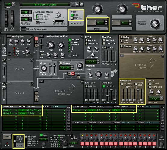
The Thor Button Cycler, showing all the changes that need to be made to the Thor init patch

Now when you press button 1, you’ll notice that the Step sequencer moves forward one step when turned on, and another step when turned off. In essence, we’ve tricked Thor into thinking that both button “on” and button “off” should trigger the Step Sequencer to “Run.” The Global Envelope was required because it is always left on, and so can be manipulated without requiring a Midi Note to “gate” the envelope.

You can now use the Step Sequencer’s Note, Curve 1, Curve 2, Gate Length, etc. to control any aspect of the Thor patch that you like, and build up different sounds at each step of the Step Sequencer. Think of generating 16 different Bass tones or 16 different Pads, Strings, Drum sounds, or any interesting sounds you can dream up. The only limitation is that you won’t have access to the Global Envelope — a minor limitation given the fact that you can get Thor to generate 16 different sounds from a single patch.

Chiptune Sounds (Redux)

As I was experimenting one day, I stumbled upon. . .

. . . a wonderful way to create some Chiptune sounds using the Wavetable Oscillator in Thor and affect it’s “Frequency (FM)” parameter with a stepped LFO. Sometimes it’s not how crazy you can make things. Instead, it’s about keeping things ultra simple. Have a look at the video to see how I paired this Chiptune idea with the above “Button Trigger Madness” idea to create 4 different Chiptune sounds within a single Thor patch.

Here’s the video:

Creating a Sweep

This is an interesting patch that will show you an alternate use for the Velocity performance of the Patch. Since the sweep changes the Volume (along with a few other parameters) over time to sweep the sound upward to full volume, you probably don’t want to have Volume modulated by Velocity. Instead, you can use the Velocity information from the musician’s performance to adjust the speed or rate of the sweep, making it rise slowly when the keys are played softly, and faster when the keys are played harder. You could also set up a button to reverse the Velocity behavior, if you like (see my previous tutorials in this series for explanations on how this is done).

Here’s the video:

Using the FSB for Practice

Another idea I had was to take patches from one synth and transfer them over to another synth within Reason. In this video, I’ll show you how you can take one of my favorite Subtractor patches and recreate the sounds inside Thor. While not every sound from the Subtractor (or Malstrom, for that matter) can be accurately reflected in Thor — they are, for the most part, different synthesis algorithms and techniques underlying each synth — you can still get pretty close, depending on the patch you start out with. It’s good mental exercise. It will help you get to know all the synth parameters and how they work. And you have an endless array of sounds at your fingertips in the FSB.

So why not give this a try with your favorite sounds? And there’s also another reason to transfer patches from the Subtractor into Thor: At the end of the transfer, you’ll still have the Rotaries, Buttons, and step sequencer to enhance or expand on the patches — something the Subtractor lacks. So here’s the video to show you the method I used:


So that’s part five in the series. As always if you have any questions or want to contribute your thoughts and ideas, I encourage you to do so. I’m always interested in hearing new ways you’ve found to work with Reason. All my best until next time.

61 – Generative Ideas (pt. 2)

Continuing our story about creating some random generative musical ideas in Reason, I’m going to take the Random Sequencers we built previously and find some usefulness for them. So hold on to your hat. It’s going to be a bumpy ride.

Continuing our story about creating some random generative musical ideas in Reason, I’m going to take the Random Sequencers we built previously and find some usefulness for them. So hold on to your hat. It’s going to be a bumpy ride.

You can download the project files here: Generative-Ideas-Part2. The files highlight the ideas I’m covering here. Note that some of the files work for Reason 4 and some work for Reason 5. C’est la vie.

Random Glitch Box

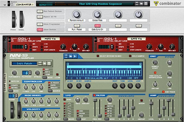
The Front panel settings on the "Glitch Box" Combinator

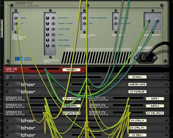
The first and probably best use I can find for these random generators is as a glitch box. Surprise surprise. This one really is a no-brainer. Just fire up the 128-step sequencer, duplicate the devices, and with a little reworking we have two separate randomizations: one for the notes and the other for the gate. Then load up a sample that spans the length of the keyboard, and this will be our “Grain Sample” which will be played via the sequencer Combinator. You can put the sample player inside the Combinator and just rewire the sound source CV / Gate inputs into your device of choice. Here, I’m going to use an NN19 for the sample.


The front of the Sampler glitch Box. It's almost like a Grain sampler, when you use the sequencer this way.


The back of the Sampler. You could also randomize the "Sample Start Time" if you wanted to go further with this idea.


Random FX

Remember that gargantuan “Key Flux FX Processor” I built oh so long ago? Well how about we fire up that bad boy and take it for the ride of its life. Using the same sequencer as above, we’ll plug it into the FX processor, and let it process any of your sounds. Just sit back and watch it cycle through all the various effects randomly. I think I could sit here for hours just listening to it doing its thing.

Crafting Some Useful Leads

Though this might not make any earth-shatteringly great lead tracks, you can make your sequencer more musical by implementing the following idea. First, take the 64-step sequencer, and change the notes around so that each of the four “Thor Sequencers” are 2-steps long. Then put the first two notes of your key (here we’ll use the key of C Major to keep it simple) into the first sequencer, the next two in the second sequencer, and so on. You will end up with this configuration:

Thor Sequencer 1: Step 1 = C3; Step 2 = D3

Thor Sequencer 2: Step 1 = E3; Step 2 = F3

Thor Sequencer 3: Step 1 = G3; Step 2 = A3

Thor Sequencer 4: Step 1 = B3; Step 2 = C4

Next, we’ll map the other steps so that we can add more of specific notes from the same key. In my patch I put more C, E, and G notes in the empty steps on the first Thor sequencer, and more of the D, F, A, B notes in the empty steps of the second Thor sequencer. I then added some sharps and flats into the third Thor sequencer, and additional suspended notes (and Octave shifts — i.e.: C4 notes) into the fourth Thor sequencer.

The steps in the first "Thor Step Sequencer" showing a C3-E3-G3-C4 pattern.

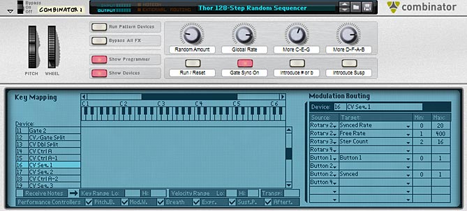
Finally, in the Combinator Modulation Routing section, I mapped the Sequencer > Step Length parameter of all four thors to Rotary 3 & 4, and Button 3 & 4 respectively. The min / max values on all were 2 / 16. This way, we can use the Rotaries and Buttons to add in further steps to increase the “weight” of them into the Random sequencer. For instance, if you turn up Rotary 1, you will introduce more C, E, and G notes. This has the effect of weighting those notes more than other notes in the key. In other words, the sequencer will “pick up” and “play” those notes more than the others.

The front of the Combinator, showing the Rotaries / Buttons. Note the Step Count is mapped to Rotary 3 to add more weight to C-E-G notes.

Of course if the Combinator had more Rotary assignments, you could weight each key separately using 8 rotaries. But that’s just not the case. But if you look at my Kongtrol articles from a few weeks back, you could very easily build it using Kong (wink wink, nudge nudge).

The patch I built only uses 1 octave range, but there’s nothing stopping you from building this across multiple octaves, up to 128 steps, using my random sequencer here. Or you can use the Transpose feature to raise it to two octaves. Or you could use the RPG-8 to force octave switches, but then you’re going to be inputting values into the “Main Sequencer” in Reason, and I’m trying to stay away from doing that.

Modulation, Modulation, Modulation

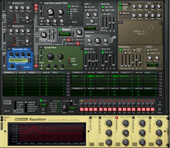
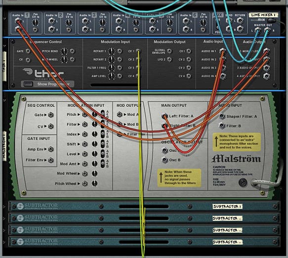
Another interesting use of the random sequencer is when you start to get into modulation. With a random setup, you can use the CV output to modulate parameters on any of the Reason devices, even ones that don’t have a CV input (using the Combinator Rotaries as the CV pass-through). Included in the file is a “Mods” patch which show you how to create a random EQ generator and also use the same random sequence to affect some parameters to the Thor sound source directly (via CV1). The Thor’s CV1 is then mapped to the “Amp Pan” and “Osc 3 Position” parameters. Note that in order to get the EQ Frequency modulated, you need to send the random sequence CV to a Combinator rotary first. Then in the Combinator’s Modulation Routing section, you can map the rotary to affect the EQ Frequency. In the patch I’m providing, I set the Min / Max values to 600 / 100, which provided some nice movement to the sound.

The front of the Combinator showing the Thor sound source and EQ, Both of which are modulated with the Thor Random Step Sequencer.


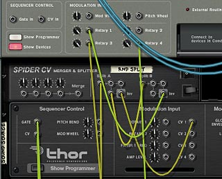
The back panel showing the Note CV sent to the Spider and then sent to Rotary 1 and the Thor sound source CV 1 input.


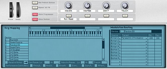
The front panel of the Combinator with the Programmer displayed. Note that the EQ Parameter 1 Frequency is mapped to Rotary 1. This way a parameter without a CV input can be controlled via CV using the Rotary as a pass-through.

In a nutshell, if you open this patch, you can press play on the transport, which starts the sound. No modulation is affecting the EQ, Pan, or Osc 3 Position parameters yet. In order to turn on these modulations, press button 1 (Run / Reset). You will then hear the modulations taking effect. To select the amount of modulation applied, use Rotary 1. To affect the Synced Rate of the modulations, use Rotary 2.

Note: in this kind of setup, I only used the “Note CV” value from the random sequencer. The gate CV value was not needed or used. I also removed the CV visualization DDL-1 devices, so that the patch would be accessible for both Reason 4 and Reason 5 users. Note also that the CV values are inverted through the Spider so that Rotary 1 will gain more modulation when turned to the right. If the signal wasn’t inverted, turning the Rotary to the right would produce less modulation, which is counter-intuitive in my book.

Where do you go from here?

These are just a few ideas I had when I was playing around with the Random Sequencer I created. As I went from having the first initial “problem,” I ended up with several interesting sequencer patches and ideas. This just proves that if you have a single thought or problem, and you can solve it, you can end up going in a lot of different directions which lead to even more ideas and creative projects. So I guess my point is this. Find as many “problems” as you can, and then work toward solving them. Because that just might be the creative spark you need to start an imaginative wildfire.

One other place you could take this is to build an entire “generative” song, in which all parts of it are randomized. In this case, if you used the Thor sequencer here, you would end up with a song that is never the same way twice, and one which bypasses the Main Reason sequencer entirely. As a creative project, that would be quite an undertaking. But if you want creative ideas, there they are.

Another creative “generative” idea is to blend multiple LFOs together, so that you end up with a lot of variety. You could then take a third LFO and use that to apply to one of the two LFO’s rate or amount parameter. There’s all kinds of ways you can layer LFOs to come up with some pretty intricate modulation sources. But I think I’ll save that one for another article at a later date. For now, I’m pretty much done looking at Thor’s sequencer for a while. And it’s Music Making Month, so it’s time to actually make some music right?

PS: If you come across any other ideas related to this idea of “Generative” or “Random” music, please share them. I’d love to hear and take a look at what you’re working on. All my best for now.

Thor Tremolo-Pan-Freq FX

This patch came out of a request to have a Tremolo effect in Reason. There’s many ways you can create one. But this time I wanted to expand upon that a little bit and create a triple effect using a single Thor device. So here is a Tremolo / Pan / Frequency Modulation effect patch that you can use.

This patch came out of a request to have a Tremolo effect in Reason. There’s many ways you can create one. But this time I wanted to expand upon that a little bit and create a triple effect using a single Thor device. So here is a Tremolo / Pan / Frequency Modulation effect patch that you can use.

Download the 2 Combinator patches here in zip file format: thor-tremolo-pan-freq-fx. Note: You will need Reason 5 or above to use the Combinators, because they both use the CV inputs on the Combinator, which was a new feature of Reason 5. If you have a previous version of Reason, the Combinator will give you a “bad format” error message.

(FX) Thor Tremolo-Pan-Frequency Combinator

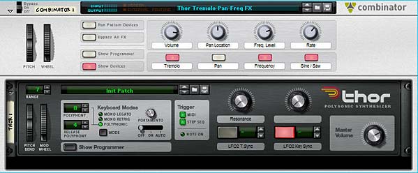
Thor Triple effect patch: Tremolo, Pan, and Frequency Modulations

This patch uses the Combinator Mod Wheel to trigger the level of the effect(s) in question. The patch is very simple in design, using only a single Thor inside the Combinator. The LFO 2 in Thor is used to modulate the following 3 effects:

  1. Tremolo
  2. Pan Modulation
  3. Frequency Modulation

Note: You must use the Mod Wheel in order to trigger these effects. You won’t hear anything happening to your audio if you don’t use the Mod Wheel!

The other nice thing about this patch is that you can have any combination of these three effects running at the same time. Or you can use only one of the effects at a time. The choice is yours.
The following explains how the patch rotaries and buttons work:

Pitch Bend: This parameter is not used.

Mod Wheel: Controls the level of the effects globally (i.e.: all three at once).

Rotary 1: Volume – Controls the global volume of the audio going out of the Combinator via the Master Level on the Thor device.

Rotary 2: Pan Location – Controls the location of the Audio in the stereo field. If the Pan modulation is turned on (see Button 2), then the panning still floats from left to right and back again like a pendulum, however, the Pan location is static and can be set anywhere along the stereo field. Try using this rotary in tandem with the Pan modulation turned on to get a feel for it.

Rotary 3: Frequency Level – Controls the Frequency of the incoming audio. Fully right cuts off the frequency entirely. Fully left opens the frequency completely. Use this in tandem with the Frequency Modulation enabled (see Button 3) for some interesting effects.

Rotary 4: Rate – This controls the rate of Thor’s LFO 2, which affects the modulation of the three effects globally.

Button 1: Tremolo – Turns on the Tremolo effect, which basically modulates the Amp Gain in Thor based on Thor’s LFO 2.

Button 2: Pan – Turns on the Panning modulation effect, which pans based on Thor’s LFO 2.

Button 3: Frequency – Turns on the Frequency modulation effect, with is modulated based on Thor’s LFO 2.

Button 4: Sine / Saw – Determines whether a Sine waveform is used or a Sawtooth wave is used. Sine is used if the button is off (disabled), and a Sawtooth waveform is used if the button is on (enabled).

And there are some extensions to this patch that I’ve set up on the Thor Rotaries and Buttons which can be accessed by Showing the Combinator devices:

Thor Rotary 1: Resonance – Controls the Resonance of Thor’s Filter 3. Minimum is set to zero (0) and Maximum is set to 96.

Thor Rotary 2: This parameter is not used.

Thor Button 1: LFO 2 Tempo Sync – Turns on the Tempo Sync for Thor’s LFO 2. When turned on, the LFO 2 Rate is tied to the song Tempo. When turned off, it is free-running.

Thor Button 2: LFO 2 Key Sync – Turns on the Key Sync for Thor’s LFO2. When turned on, the LFO 2 is re-triggered each time a key is pressed. When turned off, the LFO 2 wave is not re-triggered.

(FX) Thor Vibrato-Tremolo Combinator

This patch idea came courtesy of Eric Kloeckner. He said you could create a Vibrato in Thor by sending the audio through the Chorus effect and turning down the feedback. And voila, there it was. So now, I’ve created a second patch and placed both in the download file at the top of this posting. I also separated the LFOs in Thor, so that you can adjust the two LFOs independantly; meaning, you can turn on both the Vibrato and Tremolo and have them cycling at different rates and modulate both differently as they both act on your audio. Fun stuff.

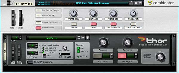
Second Thor FX Patch with separate Vibrato and Tremolo effects

The following explains how the patch rotaries and buttons work:

Pitch Bend: This parameter is not used.

Mod Wheel: Controls the level of the effects globally (i.e.: all three at once). Note again, you must use the Mod wheel to use the effect. No Mod Wheel, no effect. Very important to remember!

Rotary 1: Vibrato Delay – Controls the Chorus Delay, which can give some interesting effects and add a little more life to your Vibrato.

Rotary 2: Gain Level – Controls the Gain position of the Audio. In other words, it’s a volume level, but it’s most useful if you use it while the Tremolo is on. This way you can adjust the amount of gain (Tremolo) and the range at which the Mod Wheel affects the Tremolo.

Rotary 3: Vibrato Rate – Controls the rate of the Vibrato by adjusting the Rate of Thor’s LFO 2. In this patch, LFO 2 is tied to the Vibrato, and LFO 1 is tied to the Tremolo.

Rotary 4: Tremolo Rate – This controls the rate of the Tremolo by adjusting the Rate of Thor’s LFO 1. In this patch, LFO 2 is tied to the Vibrato, and LFO 1 is tied to the Tremolo.

Button 1: Vibrato – Turns the Vibrato effect on or off.

Button 2: Tremolo – Turns the Tremolo effect on or off.

Button 3: Vibrato Sine / Saw – Switches LFO 2 between a Sine and Sawtooth waveform, which in turn affects the shape of the Vibrato.

Button 4: Tremolo Sine / Saw – Switches LFO 2 between a Sine and Sawtooth waveform, which in turn affects the shape of the Tremolo.

And there are some extensions to this patch that I’ve set up on the Thor Rotaries and Buttons which can be accessed by Showing the Combinator devices:

Thor Rotary 1: Frequency – Controls the Frequency of Thor’s Filter 3. Minimum is set to zero (0) and Maximum is set to 127.

Thor Rotary 2: Resonance – Controls the Resonance of Thor’s Filter 3. Minimum is set to zero (0) and Maximum is set to 96.

Thor Button 1: Vibrato Tempo Sync – Turns on the Tempo Sync for Thor’s LFO 2. When turned on, the LFO 2 Rate is tied to the song Tempo. When turned off, it is free-running.

Thor Button 2: Vibrato Key Sync – Turns on the Key Sync for Thor’s LFO 2. When turned on, the LFO 2 is re-triggered each time a key is pressed. When turned off, the LFO 2 wave is not re-triggered.

Hope you find this useful. Let me know what you think?

45 – RPG-8 Arpeggio Fun (Pt.3)

And now for the third and final installment of my series which explores the RPG-8 in depth. In this tutorial, I’m going to go a little deeper and explore the CV and Pattern possibilities, using the Arpeggiator for some versatile sound control techniques.

And now for the third and final installment of my series which explores the RPG-8 in depth. In this tutorial, I’m going to go a little deeper and explore the CV and Pattern possibilities, using the Arpeggiator for some versatile sound control techniques. So let’s get started.

You can download the project files here: advanced-arp-setups. There is one .RNS file which contains the 3 setups discussed below. In addition, the 3 separate Combinators are included. The whole thing is in a zip file. Open them up to follow along with the ideas below.

The RPG-8 CV Inputs

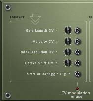
The 5 CV inputs on the back of the RPG-8 Monophonic Arpeggiator
The 5 CV inputs on the back of the Arpeggiator

Before jumping into the setups, it’s important to know some of the more advanced CV options that are available on the back of the RPG-8 device. These include the following 5 CV inputs:

  1. Gate Length CV In
  2. Velocity CV In
  3. Rate / Resolution CV In
  4. Octave Shift CV In
  5. Start of Arpeggio Trig In

Note that if you use any of these CV connections, the changes that they affect on your Arpeggio will not be reflected if you “Copy Arpeggio Notes to Track.” In other words, if you see the blinking light at the bottom of the CV connections on the back, AND you copy your arpeggio notes to track, the notes will not sound as intended (or with any CV input changes). But as I said in the first part of this series, there’s really very little need for you to copy the notes to track in the first place. Instead, keep any RPG-8 devices included in the .RNS file. This way, you’ll never come up against this problem.

Note: When using the CV inputs, the incoming CV is merged together with the setting on the front panel. For example, if your Gate Length is set to 40, and a CV value of +10 is sent to the Gate Length CV Input, then the resulting Gate Length will be 50. Same goes for the first 4 CV inputs. “Start of Arpeggio Trig In” is either in an “on” or “off” state, and therefore, this rule doesn’t apply.

If you look at how this graphs to the front of the RPG-8, you can make the following connections, which should help you to visualize what part of the RPG-8 is being controlled via CV:

The front of the RPG-8 highlighting which parameters can be modulated via CV input (on the back).

If you think about this for a moment, it takes a little to wrap your head around the concept. You are using CV to control a device, which in turn controls another device. That’s the gist of it. So armed with this knowledge, here are a few Arpeggiator setups to showcase some advanced Arpeggiator setups. Bear in mind there are probably a million and one ways to set things up. This is simply just a little taste of what can be done.

Note: For the following setups, you should add a simple chord that runs the length of 4-8 bars in a clip on the Combinator’s sequencer track. Then set the Left / Right locators at the start/end of the clip. In the transport bar, click the “Loop” button  so that the clip loops over and over (see the project download .RNS file for reference).  This ensures you can hear the effect of the Arpeggiator (s) as you play around with the settings.

Using 2 Arpeggiators to Control a Single Sound Source

This is a great way to get familiar with using both the CV input connections, as well as the Pattern section. First, let’s look at the video, and then I’ll briefly outline the setup.

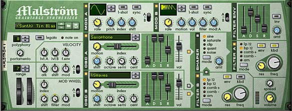
In this setup, you create a Combinator with a 6:2 line mixer. Then create a Malstrom. Set up a basic sound, as shown below. Then add an RPG-8 device underneath the Malstrom. It will automatically be routed to the Malstrom’s Note / Gate CV inputs.

The front of the Malstrom Panel, with the sound I've chosen to showcase this Arp setup

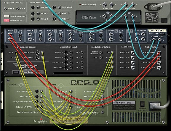
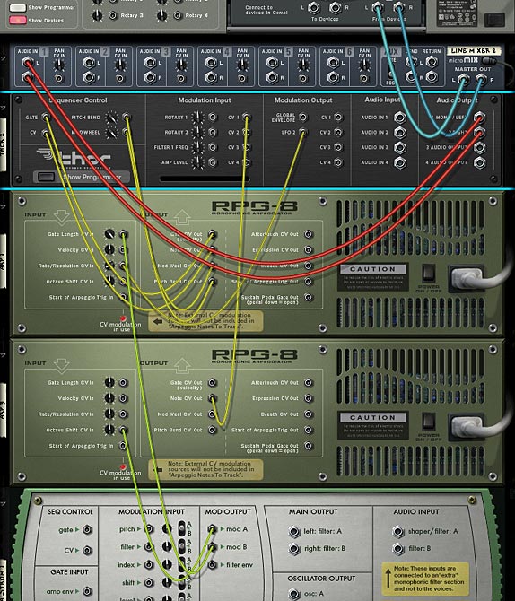
Now create another RPG-8 underneath the first. Flip it around and route the Note CV output into the “Shift” CV input on the Malstrom. Send the Gate CV output of the second RPG-8 into the “Start of Arpeggio Trig In” on the first RPG-8.  The note is now controlling the “Shift” parameter of the Malstrom’s sound. And the Gate is now controlling when the first Arpeggiator is going to start triggering (or rather, retriggering).

On the second RPG-8, press the “Pattern” button. Enter in a new pattern by skipping over a few steps (clicking the pattern step lights just above the Pattern window).

Now test it out by playing it. Notice that the notes played in the second RPG-8 determine how high or low the “Shift” parameter goes, and the “Gate” of the second RPG-8 determines the Starting of the first RPG-8 (retriggering). Since you entered a pattern on the second RPG-8, this pattern will determine when and which notes will be sent from the second RPG-8 to the first (as well as to the Malstrom).

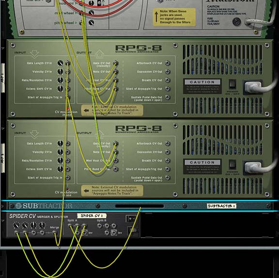
The main CV routings on the back of the rack. Note the Subtractor's LFO1 is going into the Spider A Splitter.

The real fun comes when you start applying various modulations to the Combinator Rotaries and buttons. For example, try setting the “Pattern” of the second RPG-8 as the source for Rotary 1. Now you have a real-time pattern switcher. That’s just one example.

Controlling and Controlled by a Single Sound Source

In this setup, we’ll use Thor to both Control the Arpeggiator, which in turn is used to control the note/gate of the Thor sound source. It’s kind of cannibalistic because you’re using parameters on Thor to control a device which in turn is controlling itself. But you can get some really nice results this way. Here’s how it operates:

The first thing to do is create a Combinator with a 6:2 line mixer. Then create a Thor and RPG-8 device in that sequence. Everything will be auto-routed. Add in your favorite Thor patch. After this is done, create 4 CV parameters in Thor’s Modulation Bus Routing Section (MBRS) as follows:

LFO 1 : 100 > CV Out1

Mod Env : 100 > CV Out2

LFO 2 : 100 > CV Out3

Global Env : 100 > CV Out4

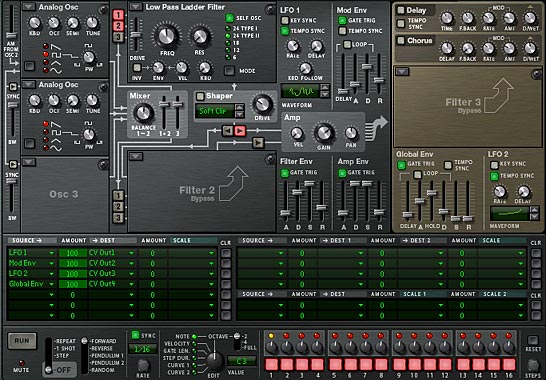
The front of the rack showing the Thor settings and MBRS routings.

In this way, Thor has four modulations that can be applied to all four CV inputs on the back of the Arpeggiator. Next, flip the rack around and lead each CV Modulation Output to the four CV inputs in the RPG-8, respectively. From there, it’s just a matter of tweaking the settings for the front panel Thor modulations, as well as the front of the RPG-8 parameters and the trim trim pots on the back of the RPG-8 (Remember that the RPG-8 CV Inputs merge the incoming signal with the front panel parameter settings, so you have to strike the right balance between the CV input trim knobs and the front panel equivalents). All three of these things (Thor modulations, RPG-8 CV input trim knobs, and RPG-8 front panel settings) determine the final sound of the Arpeggio coming out of Thor.

The back of the rack showing the Thor modulating the RPG-8, which in turn is creating Arpeggios for Thor

Bringing Multiple CV Sources together with the RPG-8

In this type of setup, I’ll use the Waveforms in a Malstrom to affect parameters in an RPG-8, and in turn use 2 RPG-8 Arpeggiators to affect a Thor sound source.

In this setup, create a Combinator with a 6:2 Line Mixer. Then create a Thor device, and RPG-8 device under that. This RPG-8 will auto-route to the Thor device. Then create another RPG-8 underneath that, and finally, holding the shift key down, create a Malstrom device under the bottom RPG-8. Make the following additional CV connections at the back of the rack:

Thor LFO 2 Output > RPG-8 1 Rate/Resolution CV Input (Trim Knob = 12)

RPG-8 2 Note CV Output > Thor’s CV 1 Modulation Input (Thor’s front MBRS panel should be “CV In1 : 100 > Osc2 Pos”)

Malstrom Mod A Output > RPG-8 2 Octave Shift CV Input (Trim Knob = 64)

Malstrom Mod B Output > RPG-8 1 Gate Length CV Input (Trim Knob = 127)

The CV routings at the back of the rack

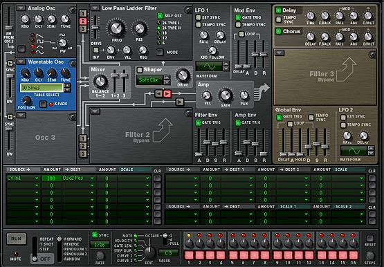
The front of the Thor device has an Analog Oscillator in the first slot and a Wavetable in the second slot, both going through a low pass ladder filter in Filter Slot 1. See below for the settings:

The settings on Thor's front panel.

Once this is done, set up the Malstrom to use both curves. The Curves should be set as follows:

Mod A:  Curve #3 (square wave) set to sync with a rate of 5/4

Mod B: Curve #2 (double saw wave) set to sync with a rate of 1/4

The following shows the settings:

The Malstrom Mod A and Mod B curves used to Modulate the Arpeggio

Now take a listen to what you’ve created. As in the previous examples, let the sound loop as you make any final settings to the Curve/Rates in the Malstrom, CV trim knobs on the back of the RPG-8 devices, and Arpeggiator settings on the front of the Arp devices. Remember, what I’m providing here are just a few examples of what can be done. There’s so much more you can explore on your own. So take it as a template and come up with your own designs.

Where do you go from here?

Anywhere quite frankly. Another thought I had, which I haven’t tried yet, is to try using the Arpeggiator to control the parameters of the Thor Step Sequencer. I haven’t tried it yet or worked on anything in that respect, but I think you could definitely find innovative uses like this.

I think, when it comes to the RPG-8, there are several interesting possibilities. Just always keep in mind the notes on the sequencer need to be on the Arpeggiator track. This one tip is the one that most pops up when people are trying to figure out how to use the device. So place clips either on the Arpeggiator track, or if the Arpeggiator is inside a Combinator, place the clips on the Combinator and ensure the RPG-8 is “receiving” notes in the Combinator’s Modulation section (it does by default).

So there you have it. A few different approaches to using the RPG-8 Monophonic Arpeggiator in Reason 4 or 5. As you can see, there’s a lot of flexibility to the device. Even those who claim to be purists; drawing in their notes by hand in the sequencer or playing them out on a keyboard controller should be encouraged to take a look at this versatile device. It’s not just for arpeggiating notes you know. Like Thor, there’s a lot under the hood of this device that may go unnoticed, even by professionals. I just hope this encourages them to take another look at one of my favorite Reason devices. Until next, time, thanks for reading and watching, and please leave a comment if you like what you see or you have any questions.

42 – Stacking Modulated Filters

In this tutorial I’m going to show you two things: 1. How to Stack multiple filters together to process a sound, and 2. How to use Thor’s filters to supplement other devices in Reason that don’t have those same filters (think of the Formant and some parts of the State Variable Filter).

In this tutorial I’m going to show you two things: 1. How to Stack multiple filters together to process a sound, and 2. How to use Thor’s filters to supplement other devices in Reason that don’t have those same filters (think of the Formant and some parts of the State Variable Filter).

You can download the project file here: stacking-filters. This is a zip file that contains the .rns file with the two Combinators used in the making of this tutorial. Those same two Combinators are provided separately as well. The files work with Reason 4 and above.

Stacking Thor Filters (In a Nutshell)

Before jumping into the tutorial, if you are a primarily visual person (or just a YouTube whore), you can watch the video below to see the process outlined:

It should be noted that this is merely one method to stack a few filters. I find this method gives you a lot of flexibility when it comes to processing the sound, because you can adjust the amount of filtered sound which is mixed with the original sound (in other words, parallel processing). So let’s get started.

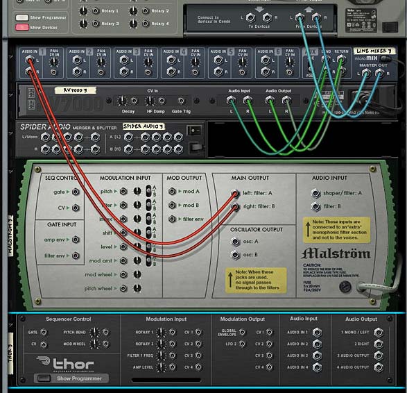
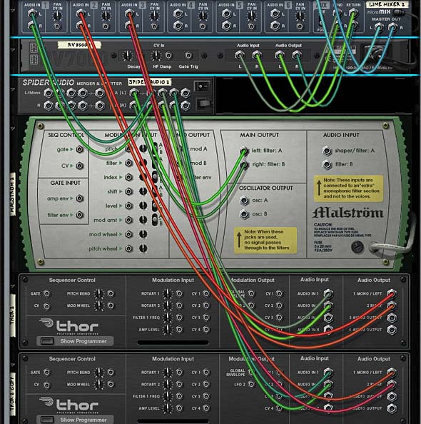
  1. First off, Create a Main 14:2 Mixer at the top of your rack. Then create a Combinator. Then inside the Combinator, create in order a 6:2 Line Mixer, RV7000, Spider Audio Merger/Splitter, and Malstrom. Then holding the shift key down (to prevent auto-routing), create a Thor synth device.
  2. Flip the rack around (Tab) and create the following routings: Remove the Malstrom Main A/B Outputs and reroute them to the Main Left/Right splits in the Audio Splitter. Then send one pair of splits to Channel 1 on the Line Mixer. Send another Split into Thor’s Audio Input 1 & 2. Then Send the Left/Right Audio outputs from Thor into Channel 2 on the Mixer.
    The view of the back of the Rack before all the routing
    The view of the back of the Rack before all the routing.

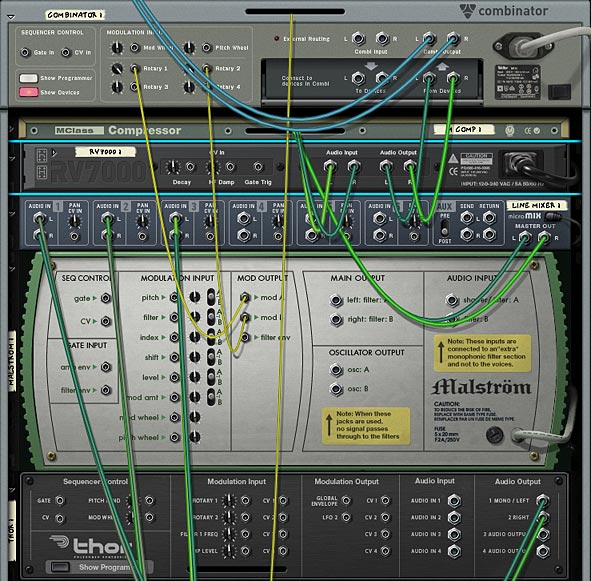
    The view at the back of the rack after all the routings -- we'll get to the second Thor's routing in a bit. . .
    The view at the back of the rack after all the routing -- we'll get to the second Thor's routing in a bit. . .
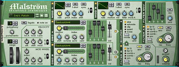
  3. Flip back around to the Front (Tab). In the Malstrom, turn on Oscillator 2, and set both Oscillators to “Sawtooth*4” and both Waveshapes in Mod A and Mod B to “Curve 2.” Set the ADSR envelopes of  both Oscillators to 40/127/127/75, respectively (This turns the sound into a much more progressive slow-moving Pad). Route Oscillator A to the Shaper and Oscillator B to the Filter B (Note: Do not turn on the Shaper). Set Filter A’s Frequency to somwhere around 116 or so. Set Filter B’s Frequency to somewhere around 106. This is so that we remove a bit of harshness in the final sound we’ll be building up. Set Oscillator A’s Cent value to “+7” and Oscillator B’s Cent value to “-7” which detunes the Oscillators from each other.

    The Malstrom settings
    The Malstrom settings
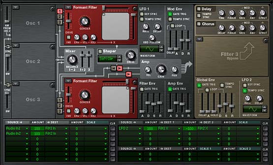
  4. Moving to the Thor, Turn Oscillator 1 Off, and uncheck the “1” button which routes Osc.1 to Filter 1. You don’t need Oscillators in Thor. We’re only using the Filters in Thor. Turn on the Formant Filter in both the first and second Filter Slots and set up Filter 1’s X/Y value to “0/127” and Filter 2’s X/Y value to “127/127.” Turn off the Filter Envelope’s “Gate Trig” button as well so that the Filters are not affected by the Filter Envelope. Then enable Filter 2 to be sent to the Amp section (the small arrow that leads from Filter 2 to Amp). Turn on the Tempo Sync for LFO2 and set the Rate to 6/4. Finally, set the Amp Envelope’s ADSR to the following values: 396 ms / 29.6 s / -0.0 dB / 6.98 s.
  5. Next, in Thor’s Modulation Bus Routing Section (MBRS), enter the following slots/lines:

    Slot 1 – Audio In1 : 100 > Filt1 In

    Slot 2 –  Audio In2 : 100 > Filt2 In

    Slot 8 – LFO2 : 100 > Filt1 X : -100 > Filt2 X

    The Thor Filter settings and Modulation Bus Routing Section (MBRS) settings.
    The Thor Filter settings and Modulation Bus Routing Section (MBRS) settings.

    The first 2 slots are telling Thor to take the audio input of the Left and Right Audio cables we set up previously, and sent them to Filter 1 and Filter 2 respectively. From that point onward, the signal travels through Thor as it normally would and then outputs to Channel 2 on the Line Mixer. The last line is what modulates the filter parameters in Thor. This basically creates a cross-over between filter 1 and filter 2 based on the default Sine wave in LFO2. Ok so far.

  6. Now with the Thor still selected, right-click and select “Duplicate Devices and Tracks.” In the duplicated Thor, set the LFO2 rate to 2/1 and change the Filter 1 X/Y value to “0/0” Then change the slot 8 line in the MBRS to the following:

    LFO2: 100 > Filt1 Y : -100 > Filt2 Y

  7. Flip the rack around and connect another split pair from the Audio Splitter to this new Thor’s Audio Input 1 & 2. Then Send the Left/Right Audio outputs from the new Thor into Channel 3 on the Mixer.
  8. Flip back around to the front of the rack and on the Line Mixer adjust the following:

    Channel 1 : Aux = 34; Level = 36; Pan = -14

    Channel 2: Aux = 50; Level = 92; Pan = 18

    Channel 3: Aux = 53; Level = 90; Pan = 22

  9. Finally, let’s take a look at the RV7000. Truth be told, you could enter whatever preset you like here which would work for a Pad sound. So enter your favorite RV7000 Patch. My settings were a low HF Damp, High EQ, with EQ turned on, and a lowering of the EQ curve on the low end with the gain set on the high EQ end to affect the midtones more than any other area. I also smoothed out the curve and made a few adjustments to the overall Reverb default “Hall” settings, as shown below.
    The RV7000 settings for the Hall Reverb
    The RV7000 settings for the Hall Reverb

    The settings for the Reverb's EQ.
    The settings for the Reverb's EQ.

Now give it a play and see how it sounds. By layering the filters and sending Left and Right to different filters that are modulated with a simple Sine wave, you can create some very complex tones that you couldn’t get using the Malstrom on its own.

Quickly Converting to a Whole New Sound

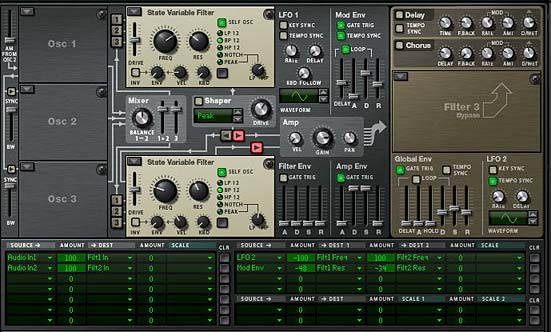
Now we can do a few interesting things with our setup. For example, duplicate the Combinator and change all four filters to “State Variable Filters.” Set the Resonance in the two filters in the first Thor to 54 and 82 respectively. In the second Thor, set both filters to “BP” mode and set the first filter’s Frequency to 3.28 kHz and Resonance to 38. Set the second filter’s Frequency to 158 kHz and Resonance to 50. Reduce the Attack and Release settings on the first Thor’s Amp Envelope a little bit. And Reduce them completely on the second Thor’s Amp Envelope. You can also use the Mod Envelope to affect the Resonance of the filters as I have done here:

Switching Filters and a few Parameters to get a completely different sound

Solo each Channel on the Mixer and see if the levels are ok. I found I had to insert a Maximizer after the second Thor just to boost things a bit. Trial and error is the key.

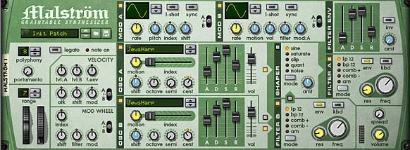
Finally, go into the Malstrom and change the two Oscillators to use the “JewsHarp” graintable in both. Reduce the Filter A & B Frequencies to your liking, and have a listen by playing a few notes. You end up with a very different sound altogether; like a slow meandering rumble. With just a few minor changes you get all sorts of different sounds.

The Malstrom Settings for this brand new sound. Use the JewsHarp Oscillators

Where do you go from here?

Anyplace you like is the short answer. But try out different filters and different Malstrom Oscillators. You could also insert a Scream device with some mild settings to completely alter the sound. Or try your hand modulating the filters in different unexpected ways using different LFO waves and rates. The sky is really the limit.

The only thing I might be wary of doing is creating delays on any of the parallel signals, as this can cause some phase shifting. But that might be something you are trying to achieve. It’s really up to you.

Let me know what you think of this tutorial and please add your comments if you come up with something far more interesting than these designs. I’d love to hear your own sound designs and creations. Until next time, good luck in all your endeavors.

40 – Thor Oscillator Wave Mods

In this tutorial I’m going to jump into Thor’s oscillators and show you how a simple method to cycle through the oscillator’s waves (Carriers, Modulators, Phase Mod Waves) can create lots of unexpected outcomes (a la Glitch). It can also allow you to modulate the Oscillators in a way you might not have thought about previously.

In this tutorial I’m going to jump into Thor’s oscillators and show you how a simple method to cycle through the oscillator’s waves (Carriers, Modulators, Phase Mod Waves) can create lots of unexpected outcomes (a la Glitch). It can also allow you to modulate the Oscillators in a way you might not have thought about previously. So let’s jump right in.

The project files can be downloaded here: Glitch-Oscillatoriffic. This zip file contains a single RNS file with 2 different Combinators. You can use the mute buttons on the main mixer to highlight each Combinator and play with each one individually.

I also wanted to say thanks to Geoff Wakefield for talking over this idea through an email exchange. Your ideas are great, as is your music Geoff! Keep up the great work. And go check out his music here: http://soundcloud.com/raven-2741.

First, here’s a video that outlines the basic concepts of modulating Thor’s oscillator waves:

Modulating Thor’s “FM Pair” Oscillator’s Carrier and Modulator

The main trick here is to keep all the devices inside a Combinator so that you can use CV to trigger the Rotaries of the Combinator. The Modulation Bus in the Combinator is used to set up the Oscillator’s Carrier and Modulation waves in the FM Pair, so that when CV is cabled into Rotary 1 & 2, the CV triggers a “cycling” through the different waves. This in turn affects the sound coming out of Thor. You then use the Malstrom’s Mod A & Mod B to supply the CV source, which is sent to the Rotary 1 & 2 CV input.

Also in the Modulation Bus of the Combinator, you’re going to set it up so that Rotary 3 and Rotary 4 (sources) are set up to adjust the Malstrom’s Mod A and Mod B (the destination). You can adjust the Min/Max settings to be as wild and crazy (full 0/31) or as tempered as you like (1/3, for example). In this way, you can not only adjust the Carrier / Modulation waves of Thor’s Oscillator with Rotary 1 and 2, but you can also adjust the Modulation Curve settings of the Malstrom’s Mod A and Mod B with Rotary 3 and 4.

Modulating Thor’s “Phase Modulation” Oscillator’s Wave 1 & 2

Now that we have the basic concept down, it’s a snap to transfer this same idea over to the Phase Modulation Wave 1 and Wave 2. Simply switch the Thor oscillator in slot 1 to “Phase Modulation” and then go back into the Combinator Modulation Bus, and change Rotary 1 and Rotary 2 as follows:

Rotary 1 > Osc 1 Phase Modulation Wave 1

Rotary 2 > Osc 1 Phase Modulation Wave 2

Note: the actual Min/Max settings, as shown earlier, can be anything you like, depending how crazy you like things.

Modulating Thor’s “Wavetable” Oscillator’s Tables

Now instead of the Phase Modulation oscillator, switch to the Wavetable Oscillator. Personally, this is my favorite oscillators for this type of technique. The variety and timbre of the sounds make it a really nice glitch mayhem device for the task. In using it though, there’s only 1 parameter we can effect, which is the actual Wavetables themselves. So switch Rotary 1 in the Combinator Modulation Bus as follows:

Rotary 1 > Osc 1 Wavetable Table

Once again, the actual Min/Max settings are up to personal taste.

One Step Further with the Oscillator’s  “Modulation” Parameter

When it comes to any of these oscillators, there is a “Modulation” parameter that you can also control using CV. For example, when using the FM Pair oscillator, you can have CV control the “FM Amount” knob. When using the Phase Modulation oscillator, you can use CV to control the “PM Amount” knob. When using the Wavetable oscillator, you can use CV to control the “Position” knob.

If you want to do this, you can borrow from one of the existing CV cables coming from the Malstrom and split it using a Spider CV Merger/Splitter, then send one split to the original Rotary destination and send another split into Thor’s CV in. Then it’s a matter of going into Thor’s Modulation Bus Routing Section (MBRS) and entering the following:

CV In1 : 100 > Osc1 FM Amt / Osc1 PM Amt / Osc1 Pos

If you set the FM/PM/Pos on Oscillator 1 very low, then using a high Amount (100) in the MBRS makes sense. If, on the other hand, you set the FM/PM/Pos knob very high, using a lower setting (-100) makes more sense. It depends which direction you want the CV to influence the knob (upward or downward).

Now that we’ve done 3 different Oscillators, I’ll leave you to work your magic on Thor’s  “Multi Oscillator” — yes, you can certainly have a lot of fun with that oscillator as well.

Bringing it all Together

If you look in the project file, you’ll see a few Combinators that take this whole idea a step further by creating a 6:2 Mixer in the Combinator, and then creating three sets of devices (each set contains a different Thor Oscillator, 1 Matrix to use the Mod A/B curves, and an Equalizer at the end of the signal chain, which is then sent to the line mixer and back out to the Combinator’s “From Device” input).

Here’s a video that goes through the steps needed to build one such Combinator:

The idea is a simple one. Have a different oscillator in each of the Thors. Set up the amp envelope any way you see fit. I find a high Decay, Sustain, and Release setting works pretty well, but again, you may have a different preference. The Malstrom Modulation Curves are there for you to use to affect the Thor oscillator waves or even the Modulation knob of the oscillator. This is where experimentation comes in.

The back of the Rack showing the main components of the Combinator and how the devices are routed.

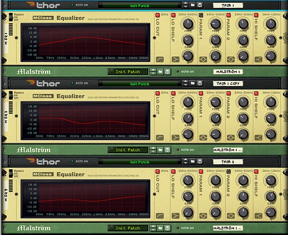
Finally, you have an Equalizer which is applied as a dynamic insert effect used to split each of the Thor sounds into their own specific range along the stereo field. This way, you can set up three oscillators and have each oscillator represent a place along the spectrum: Low, Mid and High. This way, you can balance out the sounds and let them shine in their own frequency range, without interfering with each other. Of course, these are all just suggestions. You might find some other ways to set things up for yourself.

The front of the Combinator, showing all 3 EQ devices to spread out the Oscillator sounds across Low, Mids, and Highs.

I hope this opens up some new creative avenues for you. There’s a lot more that can be done with the Thor oscillators, and this just attempts to scratch the surface or get your feet wet. Don’t be afraid to jump in though, and create your own masterpiece. Oh and if you do, please feel free to share it here. The more we see your ideas, the more we can learn from each other.

Ed’s Thor Shaper Tutorial

I’m always amazed with EditEd4TV’s ability to analyze what should be a simple signal path. He literally blows my mind when it comes to this technical stuff. And I find myself reading it about 5 times before some part of it actually sinks in. And of course the real fun comes in figuring out just “what” musically you can do with this information. So not to disappoint, Ed is back with a great tutorial on the inner workings of Thor’s Shaper feature, and more specifically the “Sine” wave inside the shaper. If you feel brave enough, my young paduan learners, then venture forward where quite honestly no man has gone before. . .

I’m always amazed with EditEd4TV’s ability to analyze what should be a simple signal path. He literally blows my mind when it comes to this technical stuff. And I find myself reading it about 5 times before some part of it actually sinks in. And of course the real fun comes in figuring out just “what” musically you can do with this information. So not to disappoint, Ed is back with a great tutorial on the inner workings of Thor’s Shaper feature, and more specifically the “Sine” wave inside the shaper. If you feel brave enough, my young paduan learners, then venture forward where quite honestly no man has gone before. . .

Download the project files here: EditEd4TV_ThorShaperFiles. They contain an Excel spreadsheet with the settings for various sine wave values/positions, as well as Ed’s 4 source cross-fader which was designed using the Shaper’s Sine wave. Quite a brilliant design idea.


Thor’s Shaper can produce a number of interesting distortion effects when processing an audio signal from any of the three oscillator slots, but one of the more arcane features of the shaper is the processing of CV data. In this setup I’m routing the mod wheel data, 0-127, into Filter 1, which is in bypass mode (no filter), which is then routed into the Shaper, set in the sine wave preset. So that you don’t bypass the learning here, I’m not providing the patch, as it’s better to get your hands dirty and learn the hard way, so let’s make this specific patch before moving on:

Processing CV data through Thor’s Shaper

  1. First, create a Thor device and initialize the preset if necessary.
  2. Next, set filter slot 1 to bypass.
  3. Deactivate oscillator 1 routing to filter 1, and activate it for filter 2.
  4. Activate the routing button to send filter 2 to the amp (it’s directly below the Shaper’s Drive knob).
  5. At this point, if you set the Step Sequencer to Repeat mode, and press the Run button, you should hear a basic repeating pulse coming from oscillator 1. If you don’t hear this, go back and check your settings before moving forward.
  6. Next, in the Step Sequencer, move the Steps knob on the far right so that we have only 1 step. For this single step, set the gate length from 75% to 100%. At this point, if you press the Run button you should hear a single pulse that drops in volume. Change the oscillator type from sawtooth to a sine wave for a more pleasant tone, and raise the amp envelope sustain level from -21.8 dB (default) to full 0.0 dB. At this point you should hear a steady sine wave tone. Again, if you don’t hear this, go back and check your settings before moving forward.
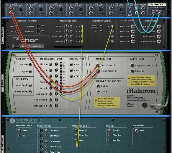
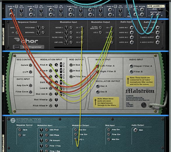
  7. In the Modulation Bus Routing Section, make the following assignment:

    Source -> Amount -> Destination -> Amount -> Scale

    Mod Wheel -> 100 -> Oscillator 1 pitch

  8. At this stage, if you raise the mod wheel you should hear the pitch rise and fall as you move the mod wheel – this is direct control with essentially linear control/results. Change this amount value to 0 for the time being.
  9. Now activate the Shaper, change the mode to Sine, and in the Modulation Bus Routing Section, make the following assignments:

    Source -> Amount -> Destination -> Amount -> Scale

    Mod Wheel -> 100 -> Filter 1 Audio Input

    Shaper -> 100 -> Oscillator 1 pitch

  10. At this stage, if you raise the mod wheel you should hear the pitch first rise, but then suddenly begin to fall. This is the sine wave of the Shaper controlling oscillator pitch. At the default of 37, you’re hearing just a portion of what’s available in this shaper setting. For a nearly perfect full sine wave cycle, set the Shaper Drive value to 50. If you listen carefully to the results, you’ll hear that with the Mod Wheel at full 127, the pitch is slightly higher than with the Mod Wheel at 0. To verify that things are off a bit, create an Analog Oscillator in oscillator slot 2, set the type to sine wave, and engage the routing button to filter 2 for oscillator 2. With the Mod Wheel at 0, you’ll hear the two oscillators in perfect sync, but with the Mod Wheel at 127, they’re off a bit. To trim this, in the Modulation Bus Routing Section, modify the previous assignment to this:

    Source -> Amount -> Destination -> Amount -> Scale

    Mod Wheel -> 100 -> Filter 1 Audio Input -> 2 -> Rotary 2

  11. You should hear Oscillator 1 pitch drop a bit. Now turn up Rotary 2 and you’ll hear the pitch rise to meet up with Oscillator 2, which is unaffected by the Mod Wheel. A Rotary 2 setting of 62 is nearly perfect. Sweep the Mod Wheel from 0 to 127 and you should hear the full sine wave cycle, landing nearly perfectly with both oscillators showing the match.

Through painstaking research, I went through and found the settings for various sine wave values/positions. You can view the chart in the Project Files download (above).

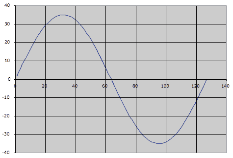
To plot out a sine wave in Excel, the magic number we’re working with is 20.21267. The A column serves as our Mod Wheel range. In the B column we find the result of a formula which works with the Mod Wheel values and multiples of the magic 20.21267 value.

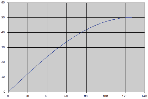
When you open the spreadsheet you’re seeing the 1/4 cycle output in the chart:

the 1/4 cycle Sine wave output

Copy the E5 to I5 range and paste into the E22 to I22 range and you’ll see the result in the chart:

a nearly perfect cycle of a sine wave

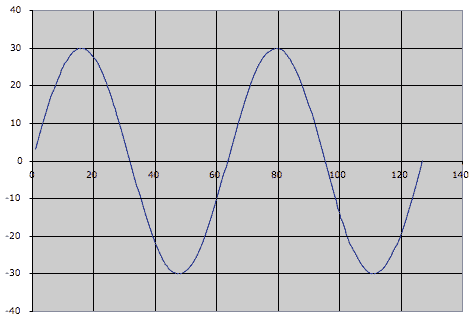
It’s a nearly perfect cycle of a sine wave. To chart out two full cycles, copy and paste E9 to I9:

Charting out 2 cycles of a Sine wave

One thing to keep in mind here is that the CV output limits change as you raise the Drive value. At a 1/4 sine wave setting (Drive value at 0 and a scale value of 34 with Rotary 2 at 0), the Shaper will output a CV value of +50 (it’s not entering the negative range of the bipolar output). At the 4 sine wave settings (Drive value at 91 and a scale value of 2 with Rotary 2 at 4) the Shaper will output a CV vale of +/- 29. The spreadsheet changes all of this for you, and adjusts the chart accordingly.

Viewing the CV value in Thor

  1. To view the CV value in Thor, let’s first make sure we’re seeing true +/-127 values from the Mod Wheel, so place this Thor inside a Combinator, and in Thor’s Modulation Bus Routing Section, make the following assignment:

    Source -> Amount -> Destination -> Amount -> Scale

    Mod Wheel -> 100 -> CV Out 1

  2. Now route CV 1 output on the back of Thor to the Combinator’s Rotary 1 input. In the Combinator’s Modulation Routing Section, make the following assignments:

    Source -> Target -> Min -> Max

    Rotary 1 -> Mod 12 Destination Amount -> -100 -> +100

    Rotary 1 -> Mod 13 Destination Amount -> -27 -> +27

  3. Change Combinator knob 1 from 63 to 64. This visualization isn’t perfect, but it’s fairly close. Raise the mod wheel and note the two amount values in Thor’s Modulation Bus Routing Section rising with the mod wheel. At full throw, they should add up to 127, and at 0 it’s approximately 0 (you may see negative values). Now modify the previous assignment to this:

    Source -> Amount -> Destination -> Amount -> Scale

    Shaper -> 100 -> CV Out 1

  4. Raise the Mod Wheel and you’ll find the values range from approximately +34 down to -36. This is basically a range of 70, so we can essentially call this +/- 35.

So… what is all this good for? What are the applications? I don’t know yet, but it does potentially open up a lot of possibilities for those folks out there with creative and curious minds. One design is a 4 source cross-fader, which is included in the Project files (download above). The Combinator is within a Reason file for maximum compatibility with everyone out there.

Inside this Combinator you’ll notice that the Shaper Driver values for “CV2” and “CV3” Thor units are set for 42, which to my ears extended the fade out time for the mixer faders to a better sounding value. The “CV2” and “CV3” Thor units are identical, except via the Combinator Modulation Routing section, CV3 Thor’s Mod Wheel values are inverted, so the full throw is 0, and the lowest position is 127. This is essentially allowing you to send that sine wave backwards (not upside down) via the Combinator knob. I know, that’s confusing a bit, but sit and stare at your screen for a few hours and it might make sense – it took a while to figure it out, and now it makes sense to me, but it wasn’t easy at first. These Thor units send bipolar CV data to raise and lower the mixer volume levels. When the values go into the negative, those CV values are of no use to the mixer, thus the channels remain at 0 volume. The other Thor, “CV1 and CV4” is sending out linear CV values as opposed to sine wave shaped values – these are being offset via a DC offset value from the two Step Sequencer CV values, one for each CV output. To add a bit of crossfade between 1&2 and between 3&4, adjust Rotary 1 on the “CV1 and CV4” Thor.

Well, that’s about it – hope this is mind-bending for you all.


Ed “EditEd4TV” Bauman

• NOW AVAILABLE ‘Reasonable Help 2010: http://baumanproductions.com/reasonablehelp.html
• Facebook: http://www.facebook.com/pages/EditEd4TV/46599212364
• Reason Files: http://www.baumanproductions.com/reason.html
• Tunes: http://www.soundclick.com/EditEd4TV

7 – Adjustable CV

Explore how to use Thor as a CV merger / splitter and Pass-Through, allowing you to set up the Combinator Rotaries so you can adjust CV levels and automate those CV changes. All of this without even breaking a sweat.

Let’s have the capability to freely adjust and automate some CV Trim Pots.

I knew that would get your attention. What? I can’t freely adjust and automate the CV trim pots on the back of the rack. What the hell is he talking about? Has he lost his mind.

Yes. I’ve lost my mind long ago. But I’ve recently found it and I’m here to try and provide a few workarounds to do things such as creating adjustable CV levels, as well as provide the ability to adjust merged and split CV sources. All without having to resort to the CV Merger/Splitter. Sound interesting? Well then let’s dig in. . .

When it comes to Thor, you’ve got a very powerful and, in my opinion, wonderfully versatile and variable sounding synth. But Thor can do a lot more than generate great synth sounds. It can perform a set of functions that no other device in the Reason arsenal can. In a previous tutorial I walked through various ways you could use Thor as an audio filter and explored a few practical uses of routing your audio through Thor. Here I’m going to explore how to use Thor as a CV merger / splitter, and furthermore, how using Thor can allow you to automate your CV trim pots, without even breaking a sweat.

The project files used for this tutorial can be downloaded here: adjustable-cv-examples. There are 6 Combinator Examples, outlining the types of tricks we’ll be doing with CV, Thor, and the Combinator Programming below. There is also the original sound source so you can compare that to all the other sounds in the 6 Combinator Examples. The Matrix tied to all the Combinators plays a single note “Drone” sound at 1/4 resolution. In order to test the examples, mute out the other channels in the main mixer except the one you are testing.

Using Thor as a CV Merger

  1. Create a Combinator, and inside the Combinator, create a 6:2 Line Mixer. Then holding shift down, create a Thor. Without holding shift down, create a Malstrom. Then once again, hold shift down and create a Subtractor.
  2. On the Subtractor, set Polyphony to 0, and press the Sync button on the LFO 1. Then duplicate the Subtractor 3 more times. On each new subtractor, select a different LFO waveform. You’ll now have 4 Subtractors with 4 different Waveforms.
  3. On the Malstrom, open the “Electric Yawn” patch under the Factory Soundbank (in the Malstrom Patches > FX folder). This is going to be our sound source.
  4. On the Thor, Initialize the Patch, and click the Show Programmer button. Turn off the Oscillator 1, and bypass Filter 1. Also click the “1” button next to Filter 1. Finally, add a Low Pass Ladder Filter into the Filter 3 slot. We’ll use 4 LFOs to affect the Filter 3 Frequency from the Thor, which in turn affects the Filtering of the Malstrom sound.
  5. Time to flip the rack around and do a little routing. Move the two audio plugs going into the Line Mixer, and plumb them into the Audio in 1 and 2 on the Thor inputs. Then plug the 1 Mono / Left and 2 Right outputs from the Thor into the Audio in on the Line Mixer’s first channel. Audio routing through Thor is setup.
  6. Next, on the back of the Subtractors, route the LFO 1 Output to the CV inputs on the back of the Thor; 1 for each of the 4 CV inputs on the back of the Thor.

    Merged CV Routing through Thor
    Merged CV Routing through Thor
  7. Flip the rack back to the front, and let’s move to the Thor’s Modulation Bus Routing Section (MBRS). On the right side of the mod bus, enter the following settings: Audio In1 > 100% > Filt3 L.In and on a second line on the right enter Audio In2 > 100% > Filt3 R.In. This sets up the Audio to be filtered through Thor.
  8. Next, on the left side of the MBRS, enter the following settings:
  9. CV In1 > 0 > Filt3 Freq.

    CV In2 > 0 > Filt3 Freq.

    CV In3 > 0 > Filt3 Freq.

    CV In4 > 0 > Filt3 Freq.

    Thor MBRS for the CV routings (left) and audio pass-through (right).
    Thor MBRS for the CV routings (left) and audio pass-through (right).
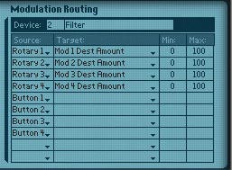
  10. Now let’s turn to the Combinator Programming. Let’s set up each Rotary to control the amount of CV applied to the Filter 3 Frequency. In this way, the Rotaries will work as the CV trim pots. So here’s where the magic happens. Set up the following modulation for the Thor:

    Rotary 1 > Mod 1 Dest Amount: 0 / 100

    Rotary 2 > Mod 2 Dest Amount: 0 / 100

    Rotary 3 > Mod 3 Dest Amount: 0 / 100

    Rotary 4 > Mod 4 Dest Amount: 0 / 100

    Combinator Programming
    Combinator Programming

This modulation setup means that you can control the Amount in the Thor Modulation Bus via the Rotary controls. It’s usually overlooked by many people. But at the bottom of the Thor’s Modulation Bus, after you scroll down through all of Thor’s parameters near the bottom lies the Modulation Destination Amount and Scaling Amount. In this way, you can control any one of the 13 modulation routings (amount and scaling).

To sum up, this Combinator we’ve created will use all 4 LFOs from the four Subtractors in unison to affect the Filter 3 Frequency of the Thor, which in turn affects the filtering of the sound source from the Malstrom. The true beauty of it all is that you can control the CV level using the Rotaries on the combinator. This works like a CV trim knob you’d find on the back of the rack.

Using Thor as a CV Pass-Through

Merging the CV signals and then controlling their level with multiple Rotaries on the Combinator are all well and good. But let’s say you don’t want to control any Thor parameters. What if you want to control an external CV source. For example, you want to control the “Shift” parameter on the Malstrom with a Subtractor LFO. This is pretty easy. Just route a CV connection from the Sub’s LFO to the Mal’s shift parameter on the back of the rack and you’re done. But you can’t control the Trim pot with this setup. So using the same kind of setup as above, here’s how you can use Thor as a Pass-Through for your CV source/destination, and at the same time tie the CV amount to a Combinator Rotary.

  1. Create a Combinator, and inside the Combinator, create a 6:2 Line Mixer. Then holding shift down, create a Thor. Without holding shift down, create a Malstrom. Then once again, hold shift down and create a Subtractor.
  2. On the Subtractor, set Polyphony to 0, and press the Sync button on the LFO 1. Select the Pulse Width waveform for the Subtractor.
  3. On the Malstrom, open the “Electric Yawn” patch under the Factory Soundbank (in the Malstrom Patches > FX folder). This is going to be our sound source.
  4. On the Thor, Initialize the Patch, and click the Show Programmer button. Turn off the Oscillator 1, and bypass Filter 1. Also click the “1” button next to Filter 1.
  5. Time to flip the rack around for our routing. On the back of the Subtractor, route the LFO 1 Output to the CV 1 Modulation Input on the back of the Thor; Then connect the CV 1 Modulation Output from Thor to the Shift Modulation Input on the Malstrom. Also turn the Shift Trim knob all the way right, so that it is completely controlled by the CV.
  6. Using Thor as a CV Pass-Through: Routing on the back of the rack
    Using Thor as a CV Pass-Through: Routing on the back of the rack
  7. Flip the rack back to the front, and let’s move to the Thor’s Modulation Bus Routing Section (MBRS). We only need one setting entered on the left side of the MBRS:
  8. CV In1 > 0 > CV Out1.

  9. Now we need to add one final programming setting on our Combinator. Open the Combinator’s Programmer, and set up Rotary 1 to control the amount of CV applied to the Shift parameter on the Malstrom. In this way, as before, the Rotary operates as the CV trim pot, moving from left (no CV applied) to fully right (100% CV applied). Set up the following modulation for the Thor:

    Rotary 1 > Mod 1 Dest Amount: 0 / 100

If you move the Rotary, you’ll hear the LFO  operating on the Shift parameter of the Malstrom. So now using this technique you can apply CV from any source to any device that has a CV input destination on the back of the rack, and also adjust the level of that CV source.

Note: if you are trying to control the Level parameter, it’s best to control your level from the Main mixer to which the sound source is connected. This way, when the Rotary is set all the way left (zero), the mixer’s channel fader will be used for the level. When all the way right (at 127), the Level is controlled 100% by CV. If, on the other hand, you try to control the level via the Malstrom’s Level CV, when the Rotary is at zero, no sound will be heard. When the Rotary is all the way right, you will hear 100% CV. So depending on what outcome you want, you may want to set this up one way or the other. The downside to routing CV from the Combinator to the Mixer’s Level CV destination is that you are setting up external routing from the Combinator. Not a problem if you save the file as an .rns instead of saving the Combi on its own. You can see this Level Pass-Through set up in one of the Combinators in the Project Files.

Using Thor as a CV Splitter

Next, we’re going to look at how you can split CV signals with Thor. This time, we’re going to send 3 CV signals to adjust 3 different CV destinations. Then we’re going to use the Combinator Rotaries to adjust the CV source level (thereby adjusting the CV amount applied to all 3 destinations at once).

  1. By now you should be getting used to the type of setup we’re using. This time we’ll create the Combinator, then inside create the Line Mixer, Thor, Malstrom (with Electric Yawn patch), and Subtractor (to use the LFO 1). Alternately, you can select and copy the Combinator from the previous example, since it already has this kind of setup created.
  2. Now we’ll flip to the back of the rack and connect the LFO1 Modulation output from the Subtractor to the CV 1 input on the Thor. Now, connect the Thor CV 1 output to the Malstrom Pitch CV input. Connect the Thor CV 2 output to the Malstrom Index CV input. Connect the Thor CV 3 output to the Malstrom Shift CV input. Finally, turn these three CV trim pots on the Malstrom all the way right.
  3. Using Thor as a CV Splitter: CV routing on the back of the rack
    Using Thor as a CV Splitter: CV routing on the back of the rack
  4. Flip the rack around again, and in the Thor MBRS, enter the following settings:
  5. CV1 > 0 > CV Out1.

    CV1 > 0 > CV Out2.

    CV1 > 0 > CV Out3.

  6. In the Combinator Programming, you can set it up 2 ways, depending. If you want to control all 3 parameters’ CV levels at once with a single Rotary, Select Rotary 1 as the source on 3 different programmer lines. Then create 3 different Destinations: Mod 1, Mod 2, and Mod 3 Dest Amount. Enter 0 and 100 for the Min / Max settings respectively. If, on the other hand, you want to have separate control over the 3 different parameters, You can change the Source so that Rotary 1 controls Mod 1 (Pitch), Rotary 2 controls Mod 2 (Index), and Rotary 3 controls Mod 3 (Shift). It all depends how you want things set up.

Note: I haven’t yet tried this, but I think you can invert the signal (just like the spider CV splitter has an “inverted” CV out). To do this in our setup above, you can set the min / max values from -100 to +100 respectively. This way, your Rotary knob will be at 0 when dead center. Moving the knob left will invert the CV signal, and moving the knob right will give a positive signal. Like I said, I haven’t tried it out, but I think I’m on solid ground here.

So there you have it. Thor can merge CV signals together, split CV signals to send the same signal to multiple destinations, and can be used as a pass-through for CV signals to affect other devices via CV. While you can do all of this with the Spider Merger/Splitter, the advantage Thor offers is that you can adjust the level of CV incoming from the source and applied to the destination, and automate this in the sequencer via the Rotaries on the Combinator. This is something that cannot be done using the Merger/Splitter alone. I hope this leads you into other avenues of exploration with Thor and CV modulation. If you have any other ideas that come to mind, please let me know. And if you have anything to add to this, please comment. I’d love to hear your thoughts.

6 – Vocoder Arp Machine

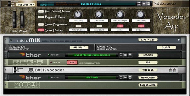
A very flexible Combinator mashup that plays an Arped up Thor run through a Vocoder. A second Thor is used to modulate the sound. Use this Combinator as a template to drop in your own Thor patches and then take it out for a spin at your next live gig. All the Combinator parameters are assigned to toy with the Arp / Vocoder settings. After all, the more flexible the Combinator is, the more use you will get out of it.

I was looking through eXode’s fabulous collection of free patches and combinators in his massive synthesis refill (available from the Propshop’s Free Refill Download Page – A must have for anyone who is looking for a great collection of new sounds!) when I came across a few patches that were hidden away with (arp) in parentheses after the patch names. Being one who loves a good arp sound I started to delve a little deeper into how it was put together. So this became the inspiration for this project. It fuses an arp with two thors — one for the modulation and another as the carrier, and both Thors feed through a Vocoder to the final output.

Now taking things a few steps further, I decided to deviate from what eXode did and add on a few modifications. Firstly, the sounds I used were completely my own (I didn’t want to copy eXode’s brilliant work). And I then took things another step further by assigning parameters to the Combinator rotaries and buttons. This way, you can use the Combi as a performance tool as well. And you can experiment with your own Thor sounds for the carrier and change the way the vocoder operates by toying with the Thor synth parameters, creating your own endless variety of Arp Vocoder machines.

So this is a bit of a mashup, being a Combinator that plays just fine as it is, or used as a template where you can drop in your own Thor patches. Finally, it can be used in live performance, since all the Combinator parameters are assigned for this purpose. After all, the more flexible the Combinator is, the more use you will get out of it.

The project files can be downloaded here: vocoder-arp. It contains an .rns file with a single Combinator which is pre-programmed to most of the major parameters you’ll need to adjust the Filter Frequency, Arp and Vocoder parameters.

Setting up the Vocoder Arp Template.

  1. First, create a Combinator, then inside the combinator create a 6:2 Line Mixer, Thor, RPG-8 Arpeggiator, BV512 Vocoder, and then holding Shift down (to disable auto routing), create another Thor. Flip the rack around and route the bottom-most Thor’s 1 Mono / Left Output to the Modulation input on the Vocoder. This is the basic setup for the arped-up vocoder. The first Thor in the Combi is the carrier, and an Arp is tied to this Thor. In other words, this is the main sound going into the Vocoder. The second Thor in the Combi is used to Modulate that Carrier sound through the Vocoder.
  2. Next, holding Shift down, create two Spider CV Merger/Spliters below the Combinator’s Line Mixer. Then hold Shift down and create a Matrix at the bottom of the stack. Set the steps to 4 and the resolution to 1/4th. Switch the Matrix mode to Curve, flip the rack around to the back and switch the curve mode to Bipolar. Then flip the rack around again and set up a curve pattern so that step 1 and 3 are +64 and step 2 and 4 are -64.
  3. The front of the Vocoder Arp with all devices
    The front of the Vocoder Arp with all devices
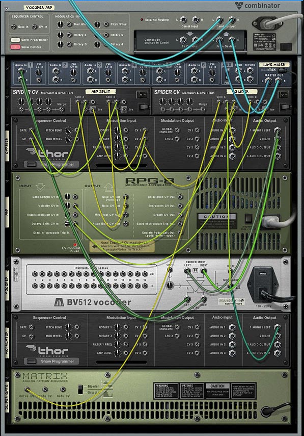
  4. Flip the rack around and on the first Spider connect the Arp Note CV out to Split A in and the Arp Gate CV out to Split B in. Connect one of the splits from Split A to the Carrier Thor’s CV in. Then connect the inverted split from Split A to the  Carrier Thor’s CV1 Modulation input. Connect one of the splits from Split B to the Carrier Thor’s Gate input, and another split from Split B to the Carrier Thor’s CV2 Modulation input.
  5. On the second Spider connect the Curve CV output from the Matrix to Split A’s input. Then connect one of the splits from Split A to the Split B input on the same Spider. Connect another split from Split A to the Vocoder Hold input. Connect the third split from Split A to the Carrier Thor’s CV3 Modulation input. Then connect the inverted split from Split A to the Arp’s Velocity CV in. on the Spider’s Split B, connect the inverted split to the Arp’s Octave Shift CV in. That just about does it for the CV routings. Luckily you can see the Combinator for yourself when you download the project files, because that was a mouthful. But it sounds more complex than it actually is.
  6. Moving to the Arp, and while you’re on the back of the rack, remove the CV cables from the Mod Wheel and Pitch Bend CV out. This way when you use the Pitch Bend, it will only affect the Thor Carrier’s Pitch Bend setting. Now flip the rack around again. Set up the Arp with an Octave Range of 2, and Insert set to Low. On the Vocoder, set the Attack to 8.
  7. The back of the rack with all the routings in place
    The back of the rack with all the routings in place
  8. Now we move to the Combinator programming. Click the Show Programmer button and enter the following settings:

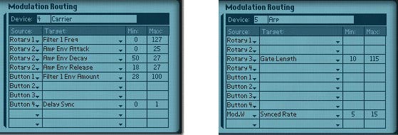
    For the Thor Carrier:

    Performance Controllers > uncheck the Mod Wheel

    Rotary 1 > Filter 1 Freq: 0 / 127

    Rotary 2 > Amp Env Attack: 0 / 25

    Rotary 2 > Amp Env Decay: 50 / 27

    Rotary 2 > Amp Env Release: 18 / 27

    Button 1 > Filter 1 Env Amount: 28 / 100

    Button 4 > Delay Sync: 0 / 1

    For the Arp:

    Rotary 3 > Gate Length: 10 / 115

    Mod.W > Synced Rate: 5 / 15

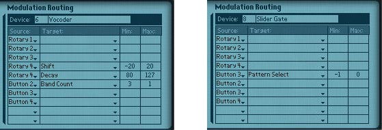
    For the Vocoder:

    Rotary 4 > Shift: -20 / 20

    Rotary 4 > Decay: 80 / 127

    Button 2 > Band Count: 3 / 1

    For the Thor Modulator:

    Performance Controllers > uncheck the Pitch Bend and Mod Wheel

    For the Matrix:

    Button 3 > Pattern Select: -1 / 0

  9. The Combi's mod programming for the Thor Carrier (left) and Arp (Right)
    The Combi's mod programming for the Thor Carrier (left) and Arp (Right)
    The Combi's mod programming for the Vocoder (left) and Matrix (right)
    The Combi's mod programming for the Vocoder (left) and Matrix (right)
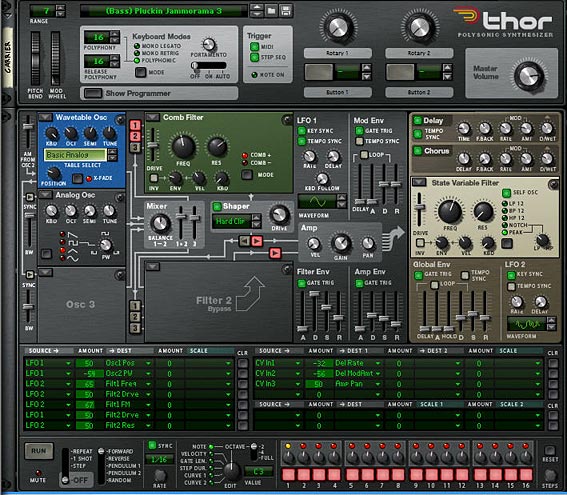
  10. Now flip the rack to the front now, and load up your favorite patch in the Thor carrier. Usually a bright lead will work best, but experiment with any sound you like. You can take a look at how I programmed the Thor in the image below. I won’t go into all the settings that were used. You can pretty much see them here. However, there are some core settings that are needed in the Modulation Bus Routing Section (MBRS) in order to have the Combinator function properly. On the right side of the Bus, create the following routings*:

    CV In1: -32 > Del Rate

    CV In2: -56 > Del ModAmt

    CV In3: 50 > Amp Pan

  11. The front of the Thor Carrier
    The front of the Thor Carrier
  12. Add a matrix below the Combinator so that it is playing the Combi. Then enter a pattern and hit play. This tests out the sounds of the Combi as you experiment with your Carrier and Modulator. For the modulator, you usually want something atonal or heavy on the noise. Unmusical is best. Droning is perfect to affect your carrier signal. This is the fun part where you toy with the Thor until you get something you like. The nice thing is that you have a wide variety of sounds to choose from using the Thor synth.

An explanation of the Combinator Programming

Pitch Bend: This affects only the Thor Carrier as you would expect a pitch bend to operate.

Mod Wheel: The Mod Wheel controls the Arp’s Synched Rate from 1/4 to 1/128th. You can use this as a performance controller to create some interesting arp variations. Let your ears be your guide on this one.

Rotary 1: This controls the full range of the Filter 1 Frequency from the Thor Carrier. Fully left and the filter is closed, fully right and the filter is fully open.

Rotary 2: This controls the Amp’s Attack, Decay, and Release from the Thor Carrier. Fully left and you’ll have very short ADR setting. Fully right and you’ll have much longer ADR settings

Rotary 3: This controls the Gate Length on the Arp. This is one of my favorite settings to play with because it can drastically alter the sounds coming from the Arp. Fully left and you have very short note lengths where the notes are staccato. Turn the knob fully right and you’ll have very long notes – to the point where the notes blend into each other much more smoothly (legato).

Rotary 4: This controls the Shift and Decay of the Vocoder at the same time, affecting the phase of the sounds you hear. This actually shifts the filters of the Vocoder’s Carrier signal down (turning the knob left) or up (turning the knob right). This can be a fun parameter to play with, and you’ll have to experiment to hear what sounds pleasant to you.

Button 1: This controls the filter envelope for the Thor Carrier’s Filter 1. Use it as a sound mode switch, and as with the Rotary 4, you’ll have to hear what sounds pleasant to your ears.

Button 2: This adjusts the band count of the Vocoder. When off, Vocoder has 32 bands. When turned on, the Vocoder has  8 bands. One note about this button: it takes a little time to catch up with itself when you alter the bands. So this may not be great for performance, and you might want to keep this button either on or off. But it’s great fun to test out your sounds through different band counts. If you don’t like these settings, you can change them in the Combinator’s Programmer to switch between any 2 bands you like.

Button 3: For lack of a better word, I named this button “Slider” — as it sounds like the notes from the Arp are being slid on the last beat of the bar. In addition, the Slider button will Pan the sound from left to right in the stereo field based on the Panning settings that were set up in the Carrier Thor’s MBRS. Remember that CV3 in we set up in the Carrier Thor? That’s affecting the Pan of the signal. In addition, the Matrix we placed at the bottom of the Combinator Device Stack is waving the sound up and down like a pulse wave. With a resolution of 1/4, the signal is synched to the 4 beats of a 4/4 tempo. But the Slider does a bit more than that. It also controls the Hold parameter of the Vocoder via CV. This means that on the fourth beat of the bar, the Vocoder is held for the duration of that last beat (one full 1/4 note). Finally, it also controls the Velocity and Octave Shift of the Arp. Yep. One of those spiders and the matrix were set up to perform a simple switch. But I thought it was a pretty cool way to affect the signal. When you turn the button on, it starts up the Matrix pattern to control everything via CV. When you turn it off, the Matrix doesn’t play any pattern at all, essentially shutting down the CV triggers.

Button 4: Finally, we have a simple switch which either keeps the Global delay of the Thor Carrier free running (when left off), or synched (turned on).


* One note about switching the Carrier Thor’s patch. If you switch the patch, you’ll have to remap the settings in the Modulation Bus section for the CV1, CV2, and CV3 sources (all the settings on the right side of the Modulation Bus section). Otherwise, the Delay and Slider functions won’t work properly. Alternatively, you don’t have to switch the patch at all. You can play with the settings in the note / global sections of the Thor until you come up with a sound you like. Point is that since this Combinator is so heavily programmed, switching patches requires a little more tweaking than normal.

Switching patches in the Modulator Thor won’t require any remapping because none of its parameters are used externally.

Any thoughts on this setup? Any ways you can see to improve it? Let me know what you think. . .