69 – All about the Alligator (Part 2)

Let’s continue with the Alligator and find a few other tricks that it can perform. In the first part, I looked at how the Alligator works, and provided a few ideas for how to work with it. In this part, I’m going to get a little more practical and show a few new ideas you can incorporate into your tunes. Hopefully this will provide you with some new creative inspiration.

Let’s continue with the Alligator and find a few other tricks that it can perform. In the first part, I looked at how the Alligator works, and provided a few ideas for how to work with it. In this part, I’m going to get a little more practical and show a few new ideas you can incorporate into your tunes. Hopefully this will provide you with some new creative inspiration.

You can download the project files here: alligator-techniques-part2. There are some Combinators and a .reason file showcasing the examples found below. In the .reason file, I’ve used mutes to silence all the tracks. To listen to a track, unmute it. I hope you find some of these tricks useful.

Also don’t forget that my latest Refill, Pureffects, is available with 1,250 effect patches designed specifically with Reason 6 in mind. There’s 200 Alligator patches alone, and several Alligator-based Combinators with all kinds of interesting routing ideas. Read More about the ReFill.

So let’s continue where we left off last. . .

Technique #5: Using the Alligator Effects without the Gates or Filters

After I wrote the first tutorial, it occurred to me that you can use each part of the Alligator independantly. For example, you can use the Gates only, without the Filter and Effects section. Or you can use the Filter section only, while keeping the Gates continually open. And lastly, you can use the Effects or Mixer sections only, if that’s all you want to use (Drive, Phaser, Delay, Pan, Volume). The way to achieve it is as follows:

  1. Start with “Technique #2: Keeping your Gates Open.” To recap, you set the pattern to #60, and ensure the Amp Envelope Decay knob is set to 127 (fully right). Then flip to the back of the Alligator, and send Gate CV Output 1 to Gate CV Input 3, Gate CV Output 2 to Gate CV Input 1, and Gate CV Output 3 to Gate CV Input 2. This way all your gates are Fully open.
  2. Fully turn down the volume of the High and Band pass filters. Note: Alternately, you can move the main left/right output cables to the Low Pass Channel left/right outputs on the back of the Alligator. This way, the audio input into the Alligator is only passing through the Low Pass section of the Alligator. Note also that this doesn’t have to be the Low Pass Channel. This idea works with any of the Channels in the Alligator, since the effects and mixer sections are the same for all 3 Channels. The idea is to pick one Channel, and mute the other two.
  3. Turn off the filter section (green light) on the low pass filter.
  4. You might also want to reduce the volume of the low pass filter (I found a volume setting of 64 for the low pass volume combined with a volume setting of 100 for the master volume is equivalent to bypassing the Alligator — at least to my ears).

Now your signal is passing through the low pass Channel only, and with the Gate always open and the Filter section turned off, you can use the effects & mixer sections independently to affect your sound.
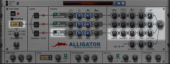
The Alligator Front Panel, showing the areas of importance when trying to use a single channel for effects and Mixer only; in this case, using the Low Pass Channel

Technique #6: Using External Effects

As with all Reason devices, you can very easily set things up to use external Reason devices. In other words, you are not limited to using the Drive, Phaser, and Delay that’s already built into the Alligator device. If you wish to use an external effects device, such as an Echo, Scream, or even any of the Kong FX modules, you can easily set this up. Here’s how you go about it.

  1. Select the sound source device or Audio Channel and then add an Alligator so that it’s auto-routed.
  2. Determine if you want the external effect to be applied to all three Channels or just one of the Channels.
  3. If you want the effect applied to all three Channels, it’s super easy. Just select the Alligator and add your effect device (a Scream, for instance). The Scream is auto-routed after the Alligator and will be applied to the Gated signal from all three Channels.
  4. If, however, you want to have the effect applied to specific Channels, select the Alligator and add your effect device (a Scream, for instance). Then flip to the back of the device (Tab), and move the main left/right Alligator audio output cables to one of the three desired Channel output pair (High, Band, or Low Pass Channel).
  5. If you desire, you can do the same thing for the other two Channels by adding other effects and routing them in a similar way. This way, you could have a Chorus effect inserted into the High Pass Channel, a Scream inserted into the Band Pass Channel, and a Pulveriser inserted into the Low Pass Channel. Or you could have three different screams inserted into the three different Channels, and set the parameters/settings for all three Screams differently to get more variation.

The more you experiment with external devices, the more I’m sure you’ll find how versatile the Alligator is in processing your sounds. You might even wonder how you ever lived without this device.
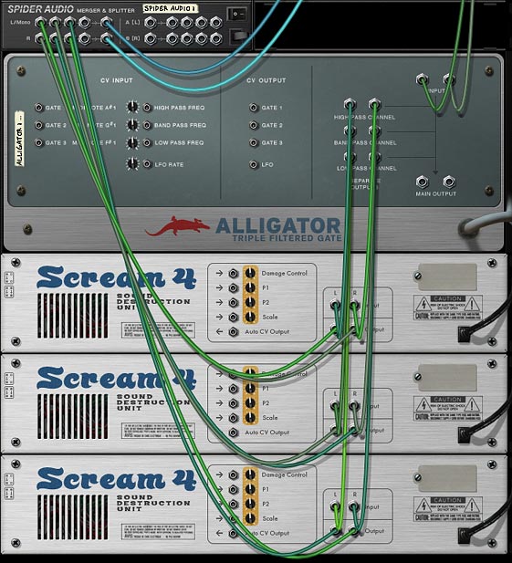
The back of the rack, showing how to process the audio through single Alligator channels and external effects.

Here’s the video showing you the above two techniques:

Technique #7: Gating Three different Audio signals across Three Different Gate Channels.

Here’s an interesting way to go about using the Alligator Effect device. How about taking three different sound sources and passing them through the three different Alligator Gate Channels, and then outputting them to three different Mixer Channels? Confused yet?

No, you can’t really do this with a single Alligator because the Alligator only has one pair of Inputs. However, you can create three Alligators, and then send your three audio sources into the three different Alligators (one audio source for each Alligator). Once this is done, you can send the separate channel outputs on to their own Mix Channel Inputs. The setup would look like this:

  • Audio Source 1 > Alligator “A” main left/right input > High Pass Channel left/right output > Mix Channel “A” left/right input
  • Audio Source 1 > Alligator “B” main left/right input > Band Pass Channel left/right output > Mix Channel “B” left/right input
  • Audio Source 1 > Alligator “C” main left/right input > Low Pass Channel left/right output > Mix Channel “C” left/right input

The nice thing about this setup is that you can choose to keep all three Alligators’ “Pattern” section the same, in which case the “Pattern” sounds sync nicely together between all three Alligators, or you can spice it up by setting up different parameters in each of the Alligator “Pattern” sections. For example, you could set Alligator “A” to have a resolution of 1/8, Alligator “B” to have a resolution of 1/16, and Alligator “C” to have a resolution of 1/32. And/or you can set all three Alligators to different patterns entirely. This way, you can attain some very intriguing and unique gate patterns going on, and all your friends will wonder how the hell you did it. Well, maybe not, but it’s something worth a try!
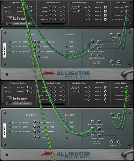
Showing different audio sources processed by different alligator channels to achieve an interesting result.

Technique #8: Oh Hell, let’s just dive off the cliff already!

You want something completely off the wall right? Well here goes. Since the Alligator contains separate outputs, you could theoretically “Nest” the Alligators one after the other. This creates a Double-Gate-Filter-FX Channel for any audio source passed through it. Here’s how this little trick works at it’s most simplest (note that you can create Triple- Quadruple- and so on, nested Channels up to the point where it probably just won’t sound good anymore and your CPU will have a heart attack and lie dead on the operation table). This technique goes down one nested level, and only highlights the “High Pass” Channel. Of course, there’s nothing stopping you from mixing/matching nested channels either. For example, a High Pass Channel goes into a Low Pass Channel, or a Low Pass Channel goes into a Band Pass Channel. Just be warned that you may need to write this out as a diagram on paper first before you lose yourself in Cables.

  • Audio Source > Alligator “A” main left/right input > High Pass Channel left/right output. . .
  • . . . Alligator “A” High Pass Channel left/right output > Alligator “B” main left/right input > High Pass Channel left/right output > Mix Channel left/right input

So now that you’ve set it up in this way, if all your Alligators are set to the exact same parameters, adding on these additional “nested” Alligators won’t produce a different sound. Where things get interesting is when you start changing the parameters so each of the Alligators are set with unique parameters. See the Project Files at the top of this tutorial for a Combinator that shows this type of setup.

Of course, if you want to use all three channels, you’ll need to create more Alligators, and each nested level will require a new Alligator. You’ll also need a Spider Audio Merger/Splitter to both split the Audio Source into the three channels, and then use the Merged side to merge them back again before going on to the Mix Channel input. As I said, this could get very tricky very quickly, and will probably be quite CPU-intensive. My advice would be to start off with one Channel and two levels (as the example shows above), then start setting up the parameters on both Alligators. See how that works out for you. Then build it up by moving to the next Channel (if you like), and so on.
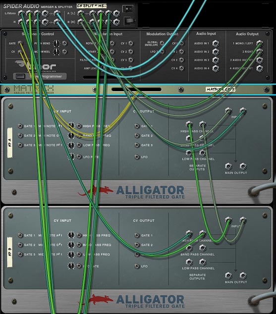
Processing your audio source through multiple Alligator Channels. This shows the High Pass Channel in series. But you can do the same with other Alligator channels.

Technique #9: Let’s Dial it Back a Bit. Adding Filter Movement

This technique is a little less freaky, and I’m going to end off with it so that you give your mind a chance to wrap around that last little technique. In this one, we’ll do something easy. We’ll take some Malstrom Curves and send them into the Alligator’s Frequency CV inputs to create some movement. Then, since there is only 2 Curve’s available with the Malstrom, we’ll steal the LFO CV output and send it into the third Filter Frequency CV input (all within the same Alligator). Sounds more complicated than it actually is. But here’s an image that shows the setup:
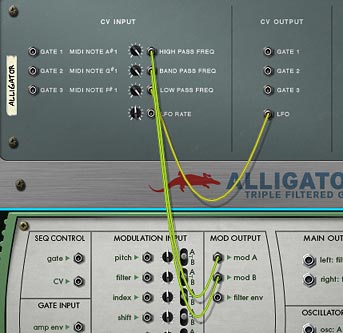
Showing the Malstrom's 2 Mod A/B waves and the Alligator's LFO to provide movement to the Alligator's 3 filters.

Those are all the ideas I have for the Alligator at the moment. I’m sure there’s many other interesting ways it can be used. If you have any other ideas, I’d love to hear them, so please don’t be shy and comment to let me know what you’ve come up with. I’m all ears. Until next time, go make some killer music. 🙂

63 – Effects Bypass Methods

This article is not so much a creative experience as it is a basic concept and educational tutorial about how to create bypasses for your effect Combinators. You can use a bypass to enable the sound travelling through the effects processor to play while the effects are turned off, and then allow the effect to affect the sound when they are turned on. In essence, it’s a way to build your Combinators so that they can be more flexible, and still allow sound to pass through; letting you decide when you want the effects built inside them to take hold of your sound.

This article is not so much a creative experience as it is a basic concept and educational tutorial about how to create bypasses for your effect Combinators. You can use a bypass to enable the sound travelling through the effects processor to play while the effects are turned off, and then allow the effect to affect the sound when they are turned on. In essence, it’s a way to build your Combinators so that they can be more flexible, and still allow sound to pass through; letting you decide when you want the effects built inside them to take hold of your sound.

This may be old hat for many of you reading here, but I’ve had a few requests for some explanations on how to split signals and create chained effects. So I thought I would put together a little piece on some different bypassing methods, since that’s vital to the core of creating multi-FX processors.

You can download the project files here: Bypass-examples. This contains a few examples of different methods you can use to Bypass effects inside a Combinator. The files are all done in Reason 5, though you can still use them if you have Reason 4 as well. This zip file also includes updated versions of the 3 Key FluX FX processors I created for a recent article. This updated version allows you to still hear the unprocessed audio signal going through the Combinator when keys are not pressed. Read on to see how I set that up.

Why would you need a bypass if the Combinator already has an Enable On/Off/Bypass switch, as well as an “Enable all Effects” button. The answer is simple. The Enable switch can click and pop if you automate it or use it while the sound is running. For this reason, I never ever under any circumstances use it. Well, okay, I do use it the odd time, but only in a situation where I’ll either keep it on, off, or bypassed the entire time the song or track is playing. I never automate it to change during a track or song. If you do, you can have undesired “pop” consequences.

As for the “Bypass all effects” and “Run Pattern Devices” buttons on the front of the Combinator, the main problem with those is the lack of automation ability. Since you can’t automate them, you’re limited in how you can use them or set them up inside your track. And why limit yourself to a bypass that can’t be automated? So while these buttons are good for previewing sounds, and getting things to run on and off while I’m creating patches or testing patches, they have very little practical use for me when I’m building a song.

So here are some of the methods I use to create an FX bypass.

The Basic Button-based Bypass (say that ten times fast).

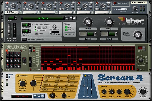
This method is probably one of the easiest and simplest of all bypasses. It allows you to build one yourself using one of the programmable Combinator buttons. We’ll start with the premise that you have created a Combinator with a 6:2 Line Mixer, added a synth (I’ll use a Thor here, but any synth or sampler will do). Then I have a Matrix playing this Thor synth. Finally, I have a simple Scream distortion unit at the end of the chain, so that the Thor synth is running through a Scream algorithm to give it some bite. This is our effect unit. And this is what we’re going to bypass.

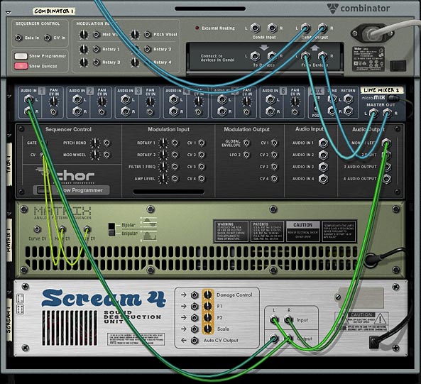
The initial device setup from the front panel in the Rack.
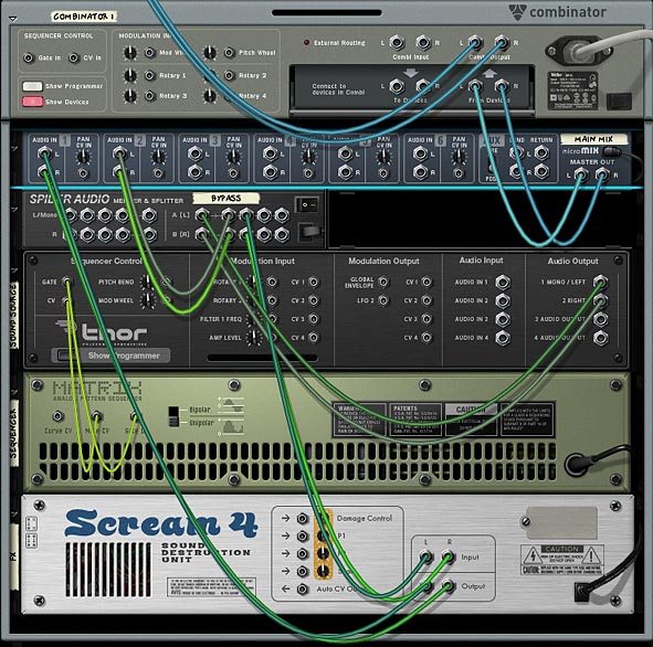
The initial device setup from the rear panel in the Rack.

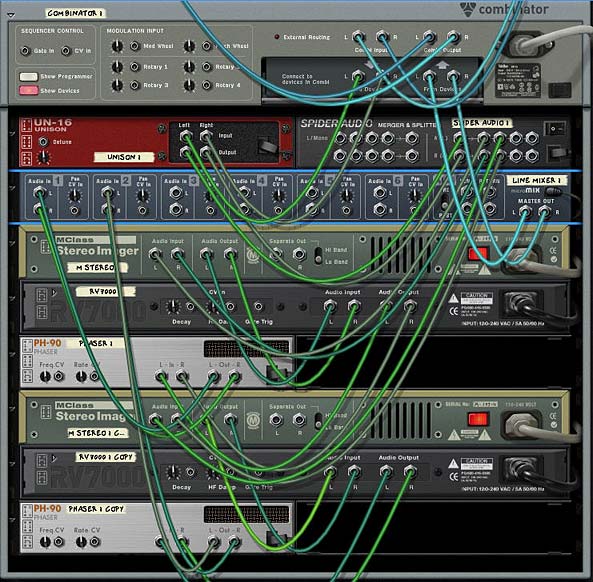
Now for the Bypass. Add a Spider audio merger/splitter between the Mixer and the Thor device. Flip the rack around (Tab) and connect the Thor left/right outputs into the Spider’s Splitter inputs. Then send one split pair out to the Line Mixer’s channel 2, and send another split pair output to the Scream input.

The back of the Rack, showing the routing which is split to 2 separate channels on the Line Mixer (using a Spider).

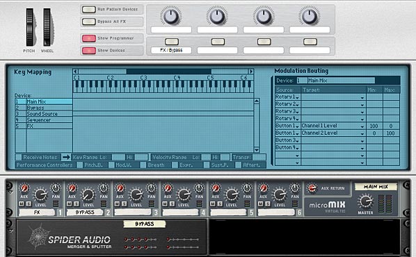
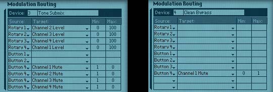
Next, flip back to the front of the Rack (Tab) and open up the Combinator programmer panel. Select the Line Mixer, and enter the following into the Modulation routing section:

Button 1 > Channel 1 Level : 100 / 0

Button 1 > Channel 2 Level : 0 / 100

This sets up Button 1 on the Combinator to switch between the two channels of the Line Mixer. If you play the sequence, you can bounce back between the FX-applied version of the sound (with the button disabled), and the bypassed (original unprocessed) version of the sound (with the button enabled). If you want to switch this around and have the bypassed version the default, just reverse the min/max amount values for Channels 1 & 2 in the Combinator’s Modulation Routing section, or else flip to the back of the rack and reverse the cable pairs going into Channels 1 & 2. That’s all there is to it.

The Button 1 setup on the Combinator, showing the Line Mixer settings and Modulation Routing.

Switching Between Three Values

This is all well and good, but there may be times that you want to switch between more than 2 parameters or channels. This can get a little more tricky, but is still relatively easy to work out. The trick involves creating a second 6:2 Line Mixer. I’ll show you what I mean below.

This idea came out of a user on the Reason forum who wanted a way to switch between Oscillator 1 and Oscillator 2, and then a Combo of both Oscillators together (1&2). I’ll use a different example here where I have a switch between 2 Scream algorithms (Scream 1 and Scream 2), and then another switch which bypasses both FX and gives you access to the original unprocessed sound. It’s the same type of idea, just implemented via FX instead of Oscillators. But if you want to read about the original question that was posted, here it is: https://www.propellerheads.se/forum/showthread.php?t=139636.

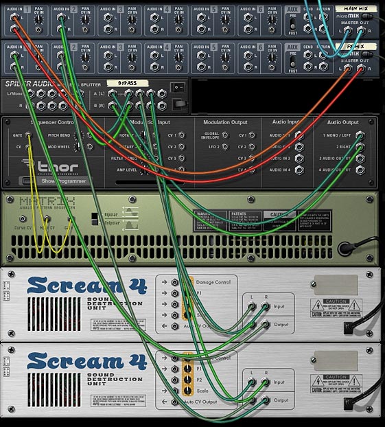
The way you do this is to first set up all the various parameters (or effects devices) to create the two different sounds. Working off the original “button-based” example above, we’ll add another Scream device below the first Scream unit (hold down Shift while you create the device, so that it’s not auto-routed). Send a new split pair from the original Spider, and have that going into the input on this “Scream 2” device.

Then create a new 6:2 Line Mixer beneath the first Line Mixer. Set up both line mixers with the following routings:

Line Mixer 1 (Main Mix):

Channel 1: Left / Right input from Line Mixer 2 (below)

Channel 2: Left / Right input from one split pair of the Spider Audio Splitter.

Note: The main left / right output goes into the “From Devices” input on the Combinator.

Line Mixer 2 (FX Mix):

Channel 1: Left / Right input from Scream 1

Channel 2: Left / Right input from Scream 2

Note: The main left / right output go into Channel 1 on Line Mixer 1 (Main Mix).

In the Combinator programmer, enter the following settings for the Modulation Routing:

Line Mixer 1 (Main Mix):

Button 2 > Channel 1 Level : 100 / 0

Button 2 > Channel 2 Level : 0 / 100

Line Mixer 2 (Main Mix):

Button 1 > Channel 1 Level : 100 / 0

Button 1 > Channel 2 Level : 0 / 100

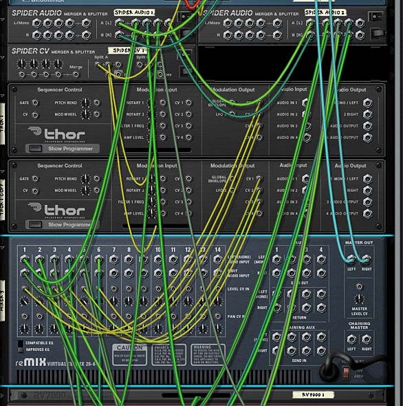
The "Triple Switch" bypass routings on the back of the Rack. It's really not as hard as it looks.

Now enable Button 1 and disable Button 2. This means the new Scream 2 device will be sounding. Note: you will first need to press each of the buttons once to “initialize” their settings. Enter some different settings on this new Scream device until you like what you hear (or load up a patch from the Factory Sound Bank).

Yes, there is a much more compact way of creating this type of scenario. It involves setting up only 2 Screams in series and then using the Combinator Modulation Routing section to enable / disable each Scream device (enabling / disabling each 3 parts of the Scream unit). But for the sake of showing how bypassing works, I’m not going to do it that way here.

With this setup, Button 1 acts as a switch between the 2 effects, and Button 2 acts as the bypass switch between those 2 effects and the original unprocessed sound. Cool right?

Bypassing FX that are on your Keys

There is another kind of bypass method that works well if you have your effects set up on keys. A perfect example of this is the “Key FluX FX Processor” Combinator I created a few articles ago. In those project files, I created a few different Combinators that were controlled by pressing the keys on your keyboard, but I failed to integrate a bypass method, so that you didn’t hear the original unprocessed sound when the keys weren’t being pressed. Essentially, you only heard a sound when the keys were pressed. So here’s a method you can use to create a bypass to hear the original unprocessed sound anytime the effects are not being played.

This method boils down to one thing: allowing the unprocessed sound to be heard when keys are not pressed. In other words, we need a way to tell Reason that when the MIDI gate is NOT triggered, let the sound pass through. When the MIDI gate IS triggered, let the effects be heard. We already have the latter part of this process set up in the patches by default. So we simply need to create a method for the former to work. Here’s how it’s done.

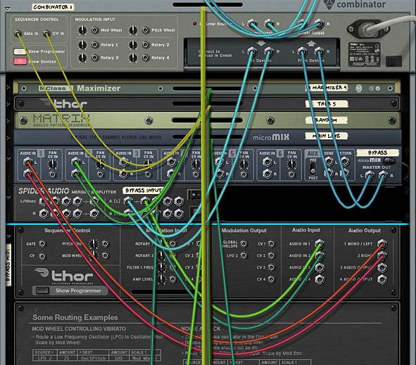
You need 3 things when creating this kind of bypass: A 6:2 Line Mixer, a Thor, and a Spider Audio Merger/Splitter. Add those into the Combinator. Take the left / right cable pair “To Devices” going from the Combinator into the Spider Splitter Left / Right input. Then send one split pair into Thor’s Audio In 1 & 2, and another split pair going out to the effects chain (in my Key FluX FX Processor patches, these cables would go into the first FX chain Spider Audio Merger / Splitter — to split the signal out to all the various keyed FX).

Then send the Left / Right audio output from Thor into the first channel of the 6:2 Line Mixer (in the image below, this is labelled “Bypass.” This Line Mixer’s second channel’s left / right input is coming from the end of the audio signal chain after all the effects. In other words, you need to send the final signal post FX processing into the second channel. This is the end of the audio line after the effects. The Line Mixer becomes the switcher, just like in the first example above, however, we’ve added an automatic component into the mix by adding the Thor device.

The back of the rack showing the routing between the Line Mixer, Spider Audio Splitter, and Thor.

So what is this Thor device doing to the audio. Before it can do anything, you need give it an explanation of what you want it to do to your audio (which is much easier than explaining the Theory of Relativity to a third grader). In the Modulation Bus Routing Section (MBRS), enter the following:

Audio In1 : 100 > Audio Out1 : -100 > MIDI Gate

Audio In2 : 100 > Audio Out2 : -100 > MIDI Gate

Thor's Modulation Bus Routing Section (MBRS) showing the negative MIDI gate scaling.

There you have it. The negative MIDI gate values mean that the original unprocessed sound will shine through when the keys are NOT played. They will also cut the sound when the keys ARE played. In this case, since you have the effects loaded on the keys, the FX signal will take over and you’ll hear the effects processing the sounds while those keys are played.

It’s important to note that negative values are possible in the MBRS and can sometimes be preferred over positive values. I say this because many beginners who are new to Reason may not be aware of how negative values can be beneficial. Case in point above. Also don’t forget you can program Mod Bus Amount and Scale values inside the Combinator’s Modulation Routing section (to switch values using a Rotary or Button). And last but not least, you can automate Amount/Scale value changes directly in the main sequencer. So you have lots of possibilities here.

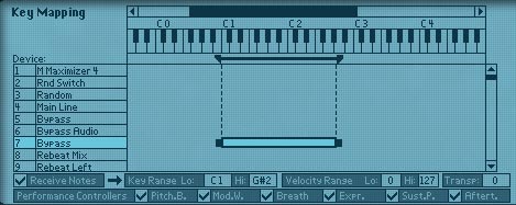
Lastly, since not all keys have effects mapped to them, you need to do one last thing. You need to map the key range of the Thor Bypass device to the same range as the keys that have effects on them. If you don’t do this, anytime you press a key that doesn’t have an effect loaded on it, you won’t hear any sound. This is because we’ve told Thor to cut out the sound on non-mapped keys. So open up the programmer, and select the “Bypass” Thor device. In the Key Mapping section of the Combinator, enter the proper Lo and Hi Key Range (near the bottom in the image below).

Mapping the key range of the effects to the Thor Bypass device in the Combinator.

Note: Since you can’t map non-contiguous regions (two separate regions with a space between the two), you need to ensure your effects are mapped to consecutive keys along the keyboard. You can’t, for example, have A1 and A2 mapped to 2 different effects without any effects mapped to the keys in between A1 and A2. This just won’t work correctly.

Pretty simple right? That’s all there is to it.

So do you have any other interesting ways of bypassing signals in Reason. I can think of a few other innovative ways to do it using CV as well. But this should at least get you started when you begin creating your own effects devices inside a Combinator. If you have any other ideas, please share them with the group. It’s always good to get more than just my own opinion on the matter. Especially since there are so many talented Reason users out there. Until next time, have fun playing inside Reason!

61 – Generative Ideas (pt. 2)

Continuing our story about creating some random generative musical ideas in Reason, I’m going to take the Random Sequencers we built previously and find some usefulness for them. So hold on to your hat. It’s going to be a bumpy ride.

Continuing our story about creating some random generative musical ideas in Reason, I’m going to take the Random Sequencers we built previously and find some usefulness for them. So hold on to your hat. It’s going to be a bumpy ride.

You can download the project files here: Generative-Ideas-Part2. The files highlight the ideas I’m covering here. Note that some of the files work for Reason 4 and some work for Reason 5. C’est la vie.

Random Glitch Box

The Front panel settings on the "Glitch Box" Combinator

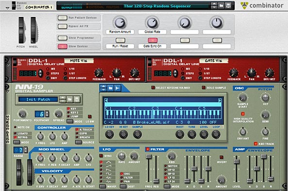
The first and probably best use I can find for these random generators is as a glitch box. Surprise surprise. This one really is a no-brainer. Just fire up the 128-step sequencer, duplicate the devices, and with a little reworking we have two separate randomizations: one for the notes and the other for the gate. Then load up a sample that spans the length of the keyboard, and this will be our “Grain Sample” which will be played via the sequencer Combinator. You can put the sample player inside the Combinator and just rewire the sound source CV / Gate inputs into your device of choice. Here, I’m going to use an NN19 for the sample.


The front of the Sampler glitch Box. It's almost like a Grain sampler, when you use the sequencer this way.


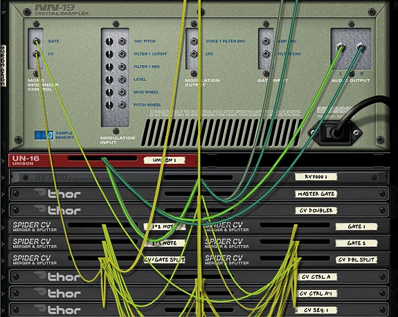
The back of the Sampler. You could also randomize the "Sample Start Time" if you wanted to go further with this idea.


Random FX

Remember that gargantuan “Key Flux FX Processor” I built oh so long ago? Well how about we fire up that bad boy and take it for the ride of its life. Using the same sequencer as above, we’ll plug it into the FX processor, and let it process any of your sounds. Just sit back and watch it cycle through all the various effects randomly. I think I could sit here for hours just listening to it doing its thing.

Crafting Some Useful Leads

Though this might not make any earth-shatteringly great lead tracks, you can make your sequencer more musical by implementing the following idea. First, take the 64-step sequencer, and change the notes around so that each of the four “Thor Sequencers” are 2-steps long. Then put the first two notes of your key (here we’ll use the key of C Major to keep it simple) into the first sequencer, the next two in the second sequencer, and so on. You will end up with this configuration:

Thor Sequencer 1: Step 1 = C3; Step 2 = D3

Thor Sequencer 2: Step 1 = E3; Step 2 = F3

Thor Sequencer 3: Step 1 = G3; Step 2 = A3

Thor Sequencer 4: Step 1 = B3; Step 2 = C4

Next, we’ll map the other steps so that we can add more of specific notes from the same key. In my patch I put more C, E, and G notes in the empty steps on the first Thor sequencer, and more of the D, F, A, B notes in the empty steps of the second Thor sequencer. I then added some sharps and flats into the third Thor sequencer, and additional suspended notes (and Octave shifts — i.e.: C4 notes) into the fourth Thor sequencer.

The steps in the first "Thor Step Sequencer" showing a C3-E3-G3-C4 pattern.

Finally, in the Combinator Modulation Routing section, I mapped the Sequencer > Step Length parameter of all four thors to Rotary 3 & 4, and Button 3 & 4 respectively. The min / max values on all were 2 / 16. This way, we can use the Rotaries and Buttons to add in further steps to increase the “weight” of them into the Random sequencer. For instance, if you turn up Rotary 1, you will introduce more C, E, and G notes. This has the effect of weighting those notes more than other notes in the key. In other words, the sequencer will “pick up” and “play” those notes more than the others.

The front of the Combinator, showing the Rotaries / Buttons. Note the Step Count is mapped to Rotary 3 to add more weight to C-E-G notes.

Of course if the Combinator had more Rotary assignments, you could weight each key separately using 8 rotaries. But that’s just not the case. But if you look at my Kongtrol articles from a few weeks back, you could very easily build it using Kong (wink wink, nudge nudge).

The patch I built only uses 1 octave range, but there’s nothing stopping you from building this across multiple octaves, up to 128 steps, using my random sequencer here. Or you can use the Transpose feature to raise it to two octaves. Or you could use the RPG-8 to force octave switches, but then you’re going to be inputting values into the “Main Sequencer” in Reason, and I’m trying to stay away from doing that.

Modulation, Modulation, Modulation

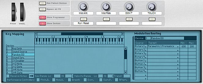
Another interesting use of the random sequencer is when you start to get into modulation. With a random setup, you can use the CV output to modulate parameters on any of the Reason devices, even ones that don’t have a CV input (using the Combinator Rotaries as the CV pass-through). Included in the file is a “Mods” patch which show you how to create a random EQ generator and also use the same random sequence to affect some parameters to the Thor sound source directly (via CV1). The Thor’s CV1 is then mapped to the “Amp Pan” and “Osc 3 Position” parameters. Note that in order to get the EQ Frequency modulated, you need to send the random sequence CV to a Combinator rotary first. Then in the Combinator’s Modulation Routing section, you can map the rotary to affect the EQ Frequency. In the patch I’m providing, I set the Min / Max values to 600 / 100, which provided some nice movement to the sound.

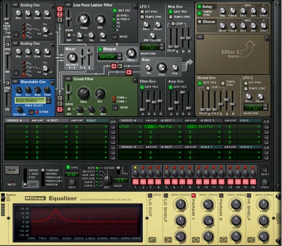
The front of the Combinator showing the Thor sound source and EQ, Both of which are modulated with the Thor Random Step Sequencer.


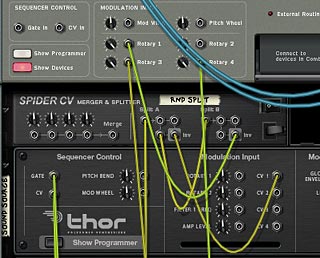
The back panel showing the Note CV sent to the Spider and then sent to Rotary 1 and the Thor sound source CV 1 input.


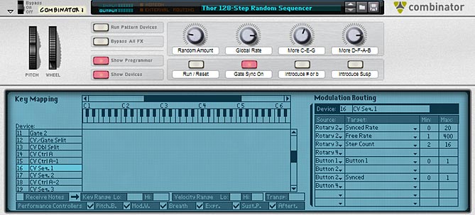
The front panel of the Combinator with the Programmer displayed. Note that the EQ Parameter 1 Frequency is mapped to Rotary 1. This way a parameter without a CV input can be controlled via CV using the Rotary as a pass-through.

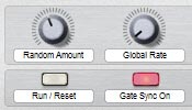
In a nutshell, if you open this patch, you can press play on the transport, which starts the sound. No modulation is affecting the EQ, Pan, or Osc 3 Position parameters yet. In order to turn on these modulations, press button 1 (Run / Reset). You will then hear the modulations taking effect. To select the amount of modulation applied, use Rotary 1. To affect the Synced Rate of the modulations, use Rotary 2.

Note: in this kind of setup, I only used the “Note CV” value from the random sequencer. The gate CV value was not needed or used. I also removed the CV visualization DDL-1 devices, so that the patch would be accessible for both Reason 4 and Reason 5 users. Note also that the CV values are inverted through the Spider so that Rotary 1 will gain more modulation when turned to the right. If the signal wasn’t inverted, turning the Rotary to the right would produce less modulation, which is counter-intuitive in my book.

Where do you go from here?

These are just a few ideas I had when I was playing around with the Random Sequencer I created. As I went from having the first initial “problem,” I ended up with several interesting sequencer patches and ideas. This just proves that if you have a single thought or problem, and you can solve it, you can end up going in a lot of different directions which lead to even more ideas and creative projects. So I guess my point is this. Find as many “problems” as you can, and then work toward solving them. Because that just might be the creative spark you need to start an imaginative wildfire.

One other place you could take this is to build an entire “generative” song, in which all parts of it are randomized. In this case, if you used the Thor sequencer here, you would end up with a song that is never the same way twice, and one which bypasses the Main Reason sequencer entirely. As a creative project, that would be quite an undertaking. But if you want creative ideas, there they are.

Another creative “generative” idea is to blend multiple LFOs together, so that you end up with a lot of variety. You could then take a third LFO and use that to apply to one of the two LFO’s rate or amount parameter. There’s all kinds of ways you can layer LFOs to come up with some pretty intricate modulation sources. But I think I’ll save that one for another article at a later date. For now, I’m pretty much done looking at Thor’s sequencer for a while. And it’s Music Making Month, so it’s time to actually make some music right?

PS: If you come across any other ideas related to this idea of “Generative” or “Random” music, please share them. I’d love to hear and take a look at what you’re working on. All my best for now.

57 – Kong FX Chain Builder

In this tutorial I’m going to show you how to create a flexible FX chain that has 8 stops along the chain, and at each of these stops, allows you to select from 1 of 6 different FX devices. This means you have a total of 48 different FX devices to select from in the chain, and the possible permutations of all these FX are 8×7 possible FX combinations, which amounts to 40,320 possible FX chain permutations.

In this tutorial I’m going to show you how to create a flexible FX chain that has 8 stops along the chain, and at each of these stops, allows you to select from 1 of 6 different FX devices. This means you have a total of 48 different FX devices to select from in the chain, and the possible permutations of all these FX are 8×7 possible FX combinations, which amounts to 40,320 possible FX chain permutations. Don’t believe me? Go here: http://www.vpgenius.com/tools/combin.aspx. That’s a hell of a lot of possibilities. Now change the order of your FX chains, and you end up with double, triple and even more possibilities. So let’s see how it’s all done.

You can download the project files here: Kong-FX-Chain-Builders. The file contains 3 different FX chain combinators that are outlined below. The effects in each chain are the same. The only difference is that they each present the chain in a different order. You can take this idea and build any number of effects chains in any order you wish to combine both “Serial” and “Parallel” processing of your audio signal through various FX that you create in Reason. It’s all only limited by your own imagination.

Introducing the “Kong FX Chain Builder” Patch

The beauty of this type of system lies also in the fact that you can combine a “Serial” and “Parallel” audio system together. So when I was working on my “Key Flux FX Processor” in project number 56 here on my site, I introduced the notion of a Parallel system, whereby the same audio was sent through many different FX chains and then sent out to the soundcard. In this tutorial, I’m going to introduce the idea of a Serial FX system, and merge it with a Parallel FX system so that you get much more flexible audio routing and audio possibilities.

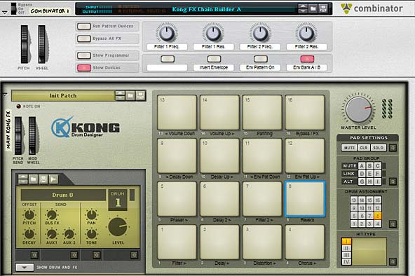
The main controls for the Kong FX Chain Builder (and Combinator Controls)

The idea is pretty simple. First you have a set of FX in a chain, as follows:

Filter > Delay > Distortion > Chorus > Phaser > Delay 2 > Filter 2 > Reverb

Now, each of these “stops” along the chain also has 7 different selectable FX sound possibilities, as follows:

Filter>

(Pad 1)

Delay>

(Pad 2)

Distortion>

(Pad 3)

Chorus>

(Pad 4)

Phaser>

(Pad 5)

Delay2>

(Pad 6)

Filter2>

(Pad 7)

Reverb>

(Pad 8 )

FX 1 FX 1 FX 1 FX 1 FX 1 FX 1 FX 1 FX 1
FX 2 FX 2 FX 2 FX 2 FX 2 FX 2 FX 2 FX 2
FX 3 FX 3 FX 3 FX 3 FX 3 FX 3 FX 3 FX 3
FX 4 FX 4 FX 4 FX 4 FX 4 FX 4 FX 4 FX 4
FX 5 FX 5 FX 5 FX 5 FX 5 FX 5 FX 5 FX 5
FX 6 FX 6 FX 6 FX 6 FX 6 FX 6 FX 6 FX 6
Dry Audio Dry Audio Dry Audio Dry Audio Dry Audio Dry Audio Dry Audio Dry Audio


The Dry audio is there so that you have a selection that sets things back to being the original audio, like a pass-through. Using this table you can come up with an amazingly large array of different sounds by mixing and matching the different FX together. You can, for instance, create the following:

Filter >

(Pad 1)

Delay >

(Pad 2)

Distortion >

(Pad 3)

Chorus >

(Pad 4)

Phaser >

(Pad 5)

Delay 2 >

(Pad 6)

Filter 2 >

(Pad 7)

Reverb >

(Pad 8 )

FX 1 FX 1 FX 1 FX 1 FX 1 FX 1 FX 1 FX 1
FX 2 FX 2 FX 2 FX 2 FX 2 FX 2 FX 2 FX 2
FX 3 FX 3 FX 3 FX 3 FX 3 FX 3 FX 3 FX 3
FX 4 FX 4 FX 4 FX 4 FX 4 FX 4 FX 4 FX 4
FX 5 FX 5 FX 5 FX 5 FX 5 FX 5 FX 5 FX 5
FX 6 FX 6 FX 6 FX 6 FX 6 FX 6 FX 6 FX 6
Dry Audio Dry Audio Dry Audio Dry Audio Dry Audio Dry Audio Dry Audio Dry Audio


And that is just one example.

Switching the Order of Effects in the Chain

The Kong FX Chain builder from the back of the rack

Now I know some of you are going to say, “well why can’t I switch the order of the FX chain?” So instead of having the Filter come before the Delay, how about switching it so that the Filter comes after the delay. And to that I’ll say that Reason is not the easiest software to work with when it comes to making routing decisions such as these and building it into a single setup is very difficult. But thankfully it’s pretty easy to build multiple instances of the Combinator to come up with any FX chain order you like. The trick is to flip to the back of the rack and change the following:

  1. The order of the “Gate Out” CVs from the first 8 Kong Pads
  2. The order of the 14:2 Submixers and their associated splitters. The signal flow goes from the “To Devices” of the Combinator into the first Effect’s splitter. Then the 14:2 Submix main output of the first effect goes into the second effect’s splitter. And so on down the chain, until the final output goes into the Pan splitter device. The Pan also has a bank of different “Global” LFO Panning selections. This can be selected on Pad 15.

So anyway, this just shows you that with a little thought, you can create a variety of FX of your own and route them in a serial way. Then use the “Parallel” processing idea to create multiple effects at each stop in the chain. Simple enough right?

Here are the other 2 effect chains I came up with. Feel free to create your own based on variations that work for you. You can either change the routing scheme as I outlined above, or you can change the actual effects at each stop. As you can see, you don’t even need to have all the FX in play within the chain. You can keep any part of the chain set to “Dry Audio” so that it will not be affecting the chain at all. This means you can make your chain simple with only 1 effect in play, all 8 in play, or any amount in between. Here are the other two effect chains I put together:

Delay > Filter > Phaser > Delay 2 > Chorus > Filter 2 > Reverb > Distortion

Phaser > Chorus > Filter > Reverb > Distortion > Delay > Delay 2 > Filter 2

Working with the “Kong FX Chain Builder”

There are 2 components to working with the Kong FX Chain Builder: 1. The Combinator and 2. The Kong device. Both work together to create your FX chain. You can also use them “Live” and play the different effects out on the pads in real-time, or else build them up in the studio until you find a combination of effects that works for your sound, and then just leave this setting as it is (or save it for future recall).

I’ll start off with the Kong device. Note that if you want to fully utilize the device, you should create a track for it in Reason or Record’s Main Sequencer. This way, you can not only play the Kong device, but also record your Kong pad changes over time. And you can also lock your pad control surface to the Kong device and another controller to the Combinator; essentially controlling them both via 2 different controllers at the same time. So here are all the Kong pad settings:

  • Pads 1 to 8: These are the 8 stops in the FX chain going from Pad 1 > 2 > 3 > 4 > 5 > 6 > 7 > 8. In the original file I created (Kong FX Chain Builder A), this goes from Filter > Delay > Distortion > Chorus > Phaser > Delay 2 > Filter 2 > Reverb. The Pads act as a cycle, starting with a dry signal, then going through 6 different possible FX. The pad cycles through these 7 positions. So each time the pad is pressed, you’ll hear a new effect inserted into the chain.
  • Pads 9 and 10: Decay Down / Decay Up – These pads will shift the decay of all the Reverb effects upward or downward. So you need to have the Reverb effect turned on (in other words, you need to have one of the 6 Reverbs enabled; not the dry signal).
    Note that there is an upper and lower limit, which, when reached, will not go any further. However, the pad can continue to go upward or downward for a few more times. This means that if you push the decay all the way to zero, and still hit the “Decay Down” pad, it will continue to move downward. So it may take a few more Pad pushes on the “Decay Up” pad to get it back to a “zero” postion (until you start hearing the decay again). This is true of all the Up/Down pads.
  • Pads 11 and 12: Envelope Pattern Down / Envelope Pattern Up – These pads will shift the matrix pattern banks upward or downward. These curve patterns are used to “play” the envelope amount on all the filters in the system. Therefore, you need to have at least one filter turned on to hear anything. You also need to have the “Env Pattern On” button (button 2 on the Combinator) enabled. There are 25 patterns on each Matrix (from A1 to D1), for a total of 50 patterns from which to select (you need to use Button 4 on the Combinator to switch between Matrix A and Matrix B).
    Note that there is an upper and lower limit, which, when reached, will not go any further. However, the pad can continue to go upward or downward for a few more times. This means that if you push the patterns all the way down to A1 on the Matrix, and still hit the “Env Pat Down” pad, it will continue to move downward. So it may take a few more Pad pushes on the “Env Pat Up” pad to get it back to the “A1” postion (and get the patterns to start moving forward again). This is true of all the Up/Down pads.
  • Pads 13 and 14: Volume Down / Volume Up – These pads will shift the global volume upward or downward. Note that there is an upper and lower limit, which, when reached, will not go any further. However, the pad can continue to go upward or downward for a few more times. This means that if you push the volume all the way down to zero, and still hit the “Volume Down” pad, it will continue to move downward. So it may take a few more Pad pushes on the “Volume Up” pad to get it back to a “zero” postion (until you start hearing the volume again). This is true of all the Up/Down pads.
  • Pad 15: Panning. You can select from 6 different Auto-panning effects, which are global and affect the signal after it has gone through all 8 effect stops in the chain. There is also a seventh “dry” position, which is on by default. The Pad cycles through all 7 positions (6 “auto-panners” and 1 “dry” position).
  • Pad 16: FX / Bypass – this allows you to switch between hearing the effects chain or hearing the original “dry” signal.

The Combinator controls are outlined below:

  • Pitch Bend: Not assigned.
  • Mod Wheel: Controls the envelope amount on all the filters. This is used in conjunction with the Envelope patterns in both Matrixes that also control the envelope amount. In other words, you can use the Mod Wheel to scale the envelope amount, and therefore, how much the envelope is affected by the patterns or not. If you wish to control the envelope amount without having any patterns control the envelope, disable button 3 on the Combinator, and then use the Mod Wheel, which will now be the only parameter affecting the amount of envelope applied to the filter(s).
    Note also that both the Mod Wheel and the Patterns affect all filter envelopes globally; both “Filter 1” and “Filter 2.” And of course, at least one filter needs to be added into the FX chain for you to hear the effect of the Mod Wheel or Patterns applied to the Filter Envelope amount.
  • Rotary 1: Filter 1 Frequency. Adjusts the Frequency of the first filter in the chain. All the filter selections for “Filter 1” are affected using this rotary, so that as long as you have one of the six filters enabled in the Filter 1 slot, the Frequency can be adjusted.
  • Rotary 2: Filter 1 Resonance. Adjusts the Resonance of the first filter in the chain. All the filter selections for “Filter 1” are affected using this rotary, so that as long as you have one of the six filters enabled in the Filter 1 slot, the Resonance can be adjusted.
  • Rotary 3: Filter 2 Frequency. Adjusts the Frequency of the second filter in the chain. All the filter selections for “Filter 2” are affected using this rotary, so that as long as you have one of the six filters enabled in the Filter 2 slot, the Frequency can be adjusted.
  • Rotary 4: Filter 2 Resonance. Adjusts the Resonance of the second filter in the chain. All the filter selections for “Filter 2” are affected using this rotary, so that as long as you have one of the six filters enabled in the Filter 2 slot, the Resonance can be adjusted.
  • Button 1: Not Assigned.
  • Button 2: Invert Envelope. This is a simple envelope invert button, and affects all filters in both the “Filter 1” and “Filter 2” slots in the FX chain.
  • Button 3: Envelope Pattern On. This turns on the envelope pattern Matrixes so that the curve pattern that is selected in Matrix A or B will affect the envelope amount of all Filters in both “Filter 1” and “Filter 2” slots in the FX chain. There are 2 parameters that both affect the Filter Envelope Amount: The pattern here, and the Mod Wheel. The higher you raise the Mod Wheel, the higher the Envelope amount. You can use a combination of the pattern and Mod Wheel to effectively “play” with the Filter Envelope Amount parameter. The reason I set it up this way is that you have ultimate control over the envelope amount. For example, you can turn off the pattern by keeping this button (button 3) disabled. Then use the Mod Wheel to scale the amount upward or leave it fully off (when the Mod Wheel is fully down). Or you can turn on the pattern and leave the mod wheel fully down to have the amount controlled solely by the pattern. Or use both in combination to play around with the envelope amount.
  • Button 4: Envelope Bank A / B. Selects between the two pattern banks (2 Matrixes) that affect the Envelope Amount parameter on all filters (read above for more information). There are 25 patterns on each Matrix (from A1 to D1), for a total of 50 patterns from which to select. Button four switches between the first 25 patterns on Matrix A (when the button is disabled) to the second set of 25 patterns on Matrix B (when the button is enabled).

Visualizing the active FX Chain

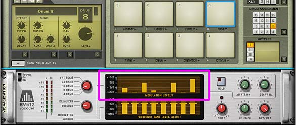
Sterioevo over at  Mute.Hate.Loud.Love was kind enough to provide two methods for visualizing the active effect chain (see the comments below this post for more info about this CV method). He used the Gate Length of the Thor Trigger devices to change the Modulation Level Bands of the BV512 Vocoder and the delay steps in the DDL delay devices to show visually which effect was enabled at each stop in the FX chain. So I updated the patches (just download the Project files again if you haven’t already) using his “Vocoder Visualization” method. You’ll now see a Vocoder under the main Kong device. This uses an 8-band setting to display the position of each effect on Pads 1-8 in the Kong device. This way you can visualize what’s going on as you play the pads. Very cool and handy little tool! Thanks Steve!

Visualizing the active FX chain using the Modulation Levels of the BV512 Vocoder

So what do you think of this combination of “Parallel” and “Serial” effects processing using Kong? Any other ideas come to mind on how these ideas can be used? I can envision setting both this and the “Key Flux FX Processor” ideas on the alternate devices. For example, you could set up the “Key Flux FX Processor” on Kong and you can probably set up the “FX Chain Builder” on a Combinator. The device is somewhat irrelevant. What matters is the concepts and what you want to accomplish. And as you can see, Reason can usually provide an avenue to make your systems come to life.

Until next time, hope you can make this work for you and use it in your own productions. If you do, drop me a line and let me see what you come up with. I’m always interested to see how others’ use my patches. Cheers for now.

56 – Key FluX FX Processor

One week, 300 + devices, enough cables to circle the earth at least once, and a massive caffeine-induced headache, here is my “Key Flux FX Processor.” If some of the other tutorials I’ve written have yet to melt your brain, then this might actually fit the bill. Here I created a massive chaotic Reason 5 FX processor. Each effect is triggered via Midi Key on the Combinator track.

If some of the other tutorials I’ve written have not yet melted your brain, then this might actually do it. It melted mine as I was creating it and I’m only just now recovering (and not in an EditEd4TV kind of way). Here, I’m going to delve into creation of a massive chaotic Reason 5 FX processor using a Combinator. And each Effect is going to be triggered via Midi Key on the Combinator track. It’s kind of like Ned Rush’s own Extreme FX Combinator (included in the NedFX refill), and Hydlide’s FX Triggering Combinator, but ummm…. yeah…. different.

So one week, 300 + devices, 84 FX chains, enough cables to circle the earth at least once, and a massive caffeine-induced headache, here is my “Key Flux FX Processor.” Ta-da!

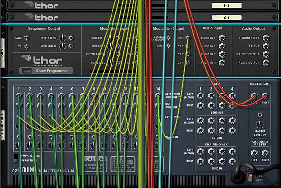
You can download the whole thing here: Key-Flux-FX-Processors. This contains the Reason 5.0 .rns and Combinator file enclosed in a zip package. Note that this is for Reason 5 users only. There’s several Kongs and the CV inputs on the Combinator are used. If I have some time, I might put together a version for R4, but right now, this is what I’ve got. Note also that your CPU will take a hit. If you have an older computer, you may not even be able to open it or use it. So I’ve included 2 “Lite” Combinators which have 21 FX chains in each. Of course there should be nothing stopping you from building your own, and you should give that a try.

The “Key Flux FX Processor” Combinator

First off, a bit about the way the Combinator operates. It is just a massive chaotic Effects processor that can be added after any sound source in Reason. So open the .rns file and take a look inside. I have a Thor patch that is being played by a matrix. And then the sound is processed through the Combinator. That’s straightforward enough. But if you press “play” on the Transport, you’ll notice you don’t hear any sound. If you want to hear the original sound, just bypass the FX Combinator.

Assuming you want to play the sound through the FX, make sure the Combinator is NOT bypassed, and instead play any key from C-2 to B4. There are 84 different effects tied to the first 84 midi keys. So playing each key will process your sound differently. Fun right?

  • Key C-2 to F1: These keys play 42 different FX chains, depending on which key you press.
  • Key F#1 to B4: These keys play 42 additional FX chains, which are combinations of the first 42.
The Combinator Key Mapping and Modulation Routing section showing each key mapped to a Thor device.
The Combinator Key Mapping and Modulation Routing section showing each key mapped to a Thor device. The Mod 1 Scale Amount scales the velocity so that Button 1 can act as a Global Velocity Sensitivity on/off switch.

Taking this a step further, you can do many different things based on the parameters that are set up on the Combinator controls, and this is where things differ greatly with the way this patch operates and others, like Ned Rush’s very awesome patch. Here are the Combinator controls:

  • Pitch Bend: Not intentionally mapped to any device, but may still provide some variations. I haven’t really gone through the whole thing to see where it’s mapped. Just kind of left this one hanging.
  • Mod Wheel: Changes the randomization pattern. 32 patterns are mapped to the Mod Wheel, and the patterns will only be heard if you have button 2 (Run Randomly) enabled.
  • Rotary 1: Parameter 1 – This knob is mapped to one or two parameters inside each of the effects chains. So utilizing it will definitely affect your sound in some weird and quirky way, no matter which effect is being played. I would caution, however, not to turn the knob before first listening to each of the effects. All the effects were built to have their parameters exactly where they are. But if you want to mangle things even more, you can do so with this knob. If you ever want to reset it back to the original values, just reload the Combinator again (of course, make sure you don’t overwrite the original file by saving over it after you’ve changed this Rotary to a different position. If you do so, all bets are off and your parameter will be permanently changed. Make sense?)
  • Rotary 2: Parameter 2 – Same as Rotary 1, except this knob is mapped to one or two “different” parameters than Rotary 1. It is mapped to at least one or two parameters inside each of the effects chains. So utilizing it will definitely affect your sound in some weird and quirky way, no matter which effect is being played. I would caution, however, not to turn the knob before first listening to each of the effects. All the effects were built to have their parameters exactly where they are. But if you want to mangle things even more, you can do so with this knob. If you ever want to reset it back to the original values, just reload the Combinator again (of course, make sure you don’t overwrite the original file by saving over it after you’ve changed this Rotary to a different position. If you do so, all bets are off and your parameter will be permanently changed. Make sense?)
  • Rotary 3: Master Volume – This is the master volume for all the effects. Sometimes things can get a little loud due to all the effects running, and while I tried to make sure all the effects are somewhat leveled out so they are all somewhere around the same volume, you can control the overall global volume using this knob. Careful not to set it too high, unless you are going for something specific, because it can go all the way up to 127 midi volume.
  • Rotary 4: Beat Delay Time – Changes the Beat Repeater time from very short (turned more left) to very long (turned more right). Used in conjunction with Button 4. In other words, you need to first turn on the Beat repeater for this to do anything.
  • Button 1: Velocity On – Turns on / off the Velocity sensitivity on a global level. So if you enable this button, you will essentially make the volume of each effect you play via your midi keys sensitive to the velocity at which you strike the keys.
  • Button 2: Run Randomly – This will turn on the Random pattern generator which randomly plays the Combinator keys. If you wish to change the rate, you’ll have to go into the “Random” matrix inside the Combinator and switch the resolution on any or all of the Matrix patterns. But this provides a nice way to randomly play the various effects in the combinator (kind of a last minute thought to add that into the mix).
  • Button 3: Beat Steps / MS – Switches the beat repeater delays from Steps (off) to milliseconds (on). Used in conjunction with Button 4. In other words, you need to first turn on the Beat repeater for this to do anything.
  • Button 4: Beat Repeat – Turns on the global beat repeater, so that you can add a beat repeat effect after any of the FX chains you are playing.

How was it all Built?

The biggest issue with building this thing was mostly time. Time to figure out the effects, and time to piece everything together. But the main concepts behind it are actually very easy to understand, so I’ll try to guide you on the building blocks and let you take things from there.

First thing’s first. You need to build all your effects chains. The easiest way to do that involves starting with one Spider Audio/Merger and sending the “To Devices” cable of the Combinator into the splitter side of the Spider. Then you can create as many more Spiders as you need, and endlessly split the signal to create as many FX chains as you like. When you have finished building your first Effects chain, send the outgoing audio signal back into a channel on a 14:2 mixer.

Second, you need to create one Thor per key (this is mostly so that you can make everything velocity sensitive by toying with the Midi Velocity setting via the “Mod Bus > Destination Scale Amount” on the front panel of the Thor in the Modulation Bus Routing Section (MBRS). In the above Modulation Routing image of the Combinator, you’ll see that each Thor has the following line:

Button 1 > Mod 1 Scale Amount: 0 / 100

In the Thor, you need to enter the following in the MBRS:

Midi Gate : 100 > CV Out1 : 0 >  Midi Vel

So in the first image below, you’ll see what needs to be placed in the front Thor panel:

The front panel of Thor, showing the MBRS line. Each key triggering Thor needs to have this same line.

And in the image below,  you’ll see how the CV1 output from each Thor is sent to the level CV input of each FX chain channel on the 14:2 mixer. Note that the trim knob for each “level cv input” on the mixer is set to full (127).

One of the FX 14:2 Submixers showing the CV from each Thor is used to trigger the level of each FX chain.

Once you’ve got one chain built and run through your Mixer, you can have fun duplicating this setup and repeating the process 42 times to fill up 3 mixers of chains on each channel. Then you can have some fun reworking the chains by combining the chains. For example, what I did in the above was create a bank of 28 Audio Spider Splitters / Mergers. I then wired the 14 Audio inputs from the first FX Submixer through the first 14 Spiders (on the split side). I then sent one split from each back to the channels on the first FX Submixer, and another split over to the Merger side of the spiders. Then on the other 14 splitters, do the same for the second FX Submixer, only be sure to send one split back to the merger side of the first 14 Spiders. Finally, send the merged output of the first 14 Spiders back to a new FX submixer. Bingo! You now have a new (fourth FX Submixer) with 14 new effects that basically combine the FX output from FX Submixer 1 and 2. I repeated this process to create a fifth FX Submixer (combining FX submixer 2 & 3), and a sixth FX submixer (combining FX submixer 1 & 3). You could actually create crossover mixes as well, for example, combine channel 1 from submix 1 to channel 5 of submix 2, etc. etc. But I didn’t want to seem like a complete lunatic! I mean 84 keys should be enough to keep you happy for a long time. Or at least until next week and a new tutorial right?

Wait. . . does anyone actually read this? hmmmm.

Ok, well then here’s the videos showcasing the sounds and what you can do with this little puppy:

And here’s a video that shows you how to build your own FX processor with velocity-sensitivity (not the whole thing, that would be CRAZY man! And it would take me hours upon hours to show you. No, this just shows you how to start things off and get the ball rolling. It’s really not a difficult concept to grasp, and it’s mostly repetition and legwork:

So now you have a system which utilizes the first 84 keys. But there’s a few more ideas I built into this whole thing. For instance, you have the global beat repeater which affects all the sounds and can be manipulated by turning it on/off on button 4. You have a simple random player which you can turn on/off via button 2. And don’t forget that when the random player is on, you can use the mod wheel to switch between 32 different patterns. If you don’t like the patterns, you can go in and change them using the first Matrix at the top of the set of Combinator devices (labelled “Random”). You also have two knobs to mangle the FX parameters, and a simple volume control on rotary 3. I honestly can’t think of too much more to pack into this little science experiment.

If the Combinator breaks your CPU. . .

It seems that there’s a lot of people that can’t open the main Combinator or run it because the FX chains inside are too much for their CPU to handle. To deal with this, I broke up the file into 2 discreet Combinators that each have 21 FX chains inside them. This way you can load up half the original FX chains and run just the ones you want. Hopefully this means that more people can use the FX. All the files are available in the project files at the top of the page. The FX can be run via keys C1 to G#2. This way, you can create some random playing via the Matrix (which is actually already built in – but it just makes it easier to tack on a Matrix after the whole thing and start adding some patterns in there to play the FX chains). There are now 2 Combinators and 2 .rns files included in the project files: “Key Flux FX Processor (Lite – A)” and “Key Flux FX Processor (Lite – B).”

Note: I have since updated these patches so that they contain a “Bypass” ability. In other words, if you don’t play the keys, the original unprocessed sound can still be heard. Then when you press the keys to hear the effects, the original sound is cut and the affected sound is passed through. For more information on how this is done, as well as the updated version of these effect Combinators, visit my Effects Bypass Methods article.


Your thoughts?

Thor Tremolo-Pan-Freq FX

This patch came out of a request to have a Tremolo effect in Reason. There’s many ways you can create one. But this time I wanted to expand upon that a little bit and create a triple effect using a single Thor device. So here is a Tremolo / Pan / Frequency Modulation effect patch that you can use.

This patch came out of a request to have a Tremolo effect in Reason. There’s many ways you can create one. But this time I wanted to expand upon that a little bit and create a triple effect using a single Thor device. So here is a Tremolo / Pan / Frequency Modulation effect patch that you can use.

Download the 2 Combinator patches here in zip file format: thor-tremolo-pan-freq-fx. Note: You will need Reason 5 or above to use the Combinators, because they both use the CV inputs on the Combinator, which was a new feature of Reason 5. If you have a previous version of Reason, the Combinator will give you a “bad format” error message.

(FX) Thor Tremolo-Pan-Frequency Combinator

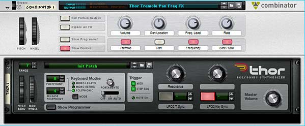
Thor Triple effect patch: Tremolo, Pan, and Frequency Modulations

This patch uses the Combinator Mod Wheel to trigger the level of the effect(s) in question. The patch is very simple in design, using only a single Thor inside the Combinator. The LFO 2 in Thor is used to modulate the following 3 effects:

  1. Tremolo
  2. Pan Modulation
  3. Frequency Modulation

Note: You must use the Mod Wheel in order to trigger these effects. You won’t hear anything happening to your audio if you don’t use the Mod Wheel!

The other nice thing about this patch is that you can have any combination of these three effects running at the same time. Or you can use only one of the effects at a time. The choice is yours.

The following explains how the patch rotaries and buttons work:

Pitch Bend: This parameter is not used.

Mod Wheel: Controls the level of the effects globally (i.e.: all three at once).

Rotary 1: Volume – Controls the global volume of the audio going out of the Combinator via the Master Level on the Thor device.

Rotary 2: Pan Location – Controls the location of the Audio in the stereo field. If the Pan modulation is turned on (see Button 2), then the panning still floats from left to right and back again like a pendulum, however, the Pan location is static and can be set anywhere along the stereo field. Try using this rotary in tandem with the Pan modulation turned on to get a feel for it.

Rotary 3: Frequency Level – Controls the Frequency of the incoming audio. Fully right cuts off the frequency entirely. Fully left opens the frequency completely. Use this in tandem with the Frequency Modulation enabled (see Button 3) for some interesting effects.

Rotary 4: Rate – This controls the rate of Thor’s LFO 2, which affects the modulation of the three effects globally.

Button 1: Tremolo – Turns on the Tremolo effect, which basically modulates the Amp Gain in Thor based on Thor’s LFO 2.

Button 2: Pan – Turns on the Panning modulation effect, which pans based on Thor’s LFO 2.

Button 3: Frequency – Turns on the Frequency modulation effect, with is modulated based on Thor’s LFO 2.

Button 4: Sine / Saw – Determines whether a Sine waveform is used or a Sawtooth wave is used. Sine is used if the button is off (disabled), and a Sawtooth waveform is used if the button is on (enabled).

And there are some extensions to this patch that I’ve set up on the Thor Rotaries and Buttons which can be accessed by Showing the Combinator devices:

Thor Rotary 1: Resonance – Controls the Resonance of Thor’s Filter 3. Minimum is set to zero (0) and Maximum is set to 96.

Thor Rotary 2: This parameter is not used.

Thor Button 1: LFO 2 Tempo Sync – Turns on the Tempo Sync for Thor’s LFO 2. When turned on, the LFO 2 Rate is tied to the song Tempo. When turned off, it is free-running.

Thor Button 2: LFO 2 Key Sync – Turns on the Key Sync for Thor’s LFO2. When turned on, the LFO 2 is re-triggered each time a key is pressed. When turned off, the LFO 2 wave is not re-triggered.

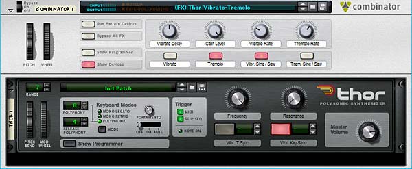
(FX) Thor Vibrato-Tremolo Combinator

This patch idea came courtesy of Eric Kloeckner. He said you could create a Vibrato in Thor by sending the audio through the Chorus effect and turning down the feedback. And voila, there it was. So now, I’ve created a second patch and placed both in the download file at the top of this posting. I also separated the LFOs in Thor, so that you can adjust the two LFOs independantly; meaning, you can turn on both the Vibrato and Tremolo and have them cycling at different rates and modulate both differently as they both act on your audio. Fun stuff.

Second Thor FX Patch with separate Vibrato and Tremolo effects

The following explains how the patch rotaries and buttons work:

Pitch Bend: This parameter is not used.

Mod Wheel: Controls the level of the effects globally (i.e.: all three at once). Note again, you must use the Mod wheel to use the effect. No Mod Wheel, no effect. Very important to remember!

Rotary 1: Vibrato Delay – Controls the Chorus Delay, which can give some interesting effects and add a little more life to your Vibrato.

Rotary 2: Gain Level – Controls the Gain position of the Audio. In other words, it’s a volume level, but it’s most useful if you use it while the Tremolo is on. This way you can adjust the amount of gain (Tremolo) and the range at which the Mod Wheel affects the Tremolo.

Rotary 3: Vibrato Rate – Controls the rate of the Vibrato by adjusting the Rate of Thor’s LFO 2. In this patch, LFO 2 is tied to the Vibrato, and LFO 1 is tied to the Tremolo.

Rotary 4: Tremolo Rate – This controls the rate of the Tremolo by adjusting the Rate of Thor’s LFO 1. In this patch, LFO 2 is tied to the Vibrato, and LFO 1 is tied to the Tremolo.

Button 1: Vibrato – Turns the Vibrato effect on or off.

Button 2: Tremolo – Turns the Tremolo effect on or off.

Button 3: Vibrato Sine / Saw – Switches LFO 2 between a Sine and Sawtooth waveform, which in turn affects the shape of the Vibrato.

Button 4: Tremolo Sine / Saw – Switches LFO 2 between a Sine and Sawtooth waveform, which in turn affects the shape of the Tremolo.

And there are some extensions to this patch that I’ve set up on the Thor Rotaries and Buttons which can be accessed by Showing the Combinator devices:

Thor Rotary 1: Frequency – Controls the Frequency of Thor’s Filter 3. Minimum is set to zero (0) and Maximum is set to 127.

Thor Rotary 2: Resonance – Controls the Resonance of Thor’s Filter 3. Minimum is set to zero (0) and Maximum is set to 96.

Thor Button 1: Vibrato Tempo Sync – Turns on the Tempo Sync for Thor’s LFO 2. When turned on, the LFO 2 Rate is tied to the song Tempo. When turned off, it is free-running.

Thor Button 2: Vibrato Key Sync – Turns on the Key Sync for Thor’s LFO 2. When turned on, the LFO 2 is re-triggered each time a key is pressed. When turned off, the LFO 2 wave is not re-triggered.

Hope you find this useful. Let me know what you think?

38 – Kong as Scene & FX Selector

Calling Kong a “Drum Designer” is like calling a Computer a “Typewriter” — sure that may have been the original intent, but it’s so much more. Here I’ll show you a whole new side to Kong. This tutorial will use Kong as a mini Scene Selector, to imitate Ableton Live’s Session view and then also use it as an Effects selector for any audio you like. In this way, you can switch between clips (Rex Loops) and Scenes (groups of Rex files). We’ll also use one of Kong’s pads to cycle through as many FX as your processor can hold. Hours of fun.

It’s very easy to think of Kong as a “Drum” designer because of course that’s what it is called. And indeed that is its primary purpose. However, it would be a mistake to think of Kong as only a “drum” programmer. That’s like calling a Computer a “Word Processor” — sure that may have been the original intent, but it’s just so much more. Here I’ll show you a whole new side to Kong. This tutorial will use Kong as a mini Scene Selector, to imitate Ableton Live’s Session view and then also use it as an Effects selector for any audio you like. In this way, you can switch between clips (Rex Loops) and Scenes (groups of Rex files). We’ll also use one of Kong’s pads to cycle through as many FX as your processor can hold. Hours of fun.

To start, I’m going to use a Combinator I came up with which you can download here: OctoKong-Scene-Selector-3. It’s a single Combinator inside an rns file. The Kong inside the Combinator has been given its own track because I find it easier to play the Kong outside the Combinator and place all the midi data there, as opposed to sequencing midi data on the Combinator track.

A little Off Tangent: Recreating Ableton “Live” in Reason?

As an aside, I have to give a huge thanks to Dioxide for inspiring the idea behind this Combinator. He wanted to try to mimic Ableton Live’s Scene / Clip system. This comes pretty close and allows you to select between different clips in a mini 9-pad way. The pads along the right side trigger all the loops within their respective rows, while the pads on top cycle through that specific row’s Rex loops (8 loops in total). When you open it up, you’ll have to press the “Run Pattern Devices” button on the Combinator. This sets all the loops running freely. I’ve also set up the first 3 buttons on the Combinator to act as your “Mutes” — so you can mute any of the columns at any point in time. You can also play each loop individually by playing the other pads alone or in combination. In this way, it’s a mini scene/clip selector for Reason.

If you’re interested, here is a 2-part series on how to create that patch:

But moving on, the real focus of this article is that lonely little pad 16 up there in the top right corner. What to do with that little pad all empty and lonely. Let’s add a ton of effects and use the pad to cycle through each of those effects one after the other. Let’s load in as many as your CPU can handle!

Well, actually, let’s focus on the PROCESS to add in as many as your CPU can handle. I’ll give you the tools and know-how to add in a few effects, maybe 4 or 5, and then you can use the same technique to load up as many effects as you like. This way, you can take the FX Pad in any direction you like. Sound good? Ok. Let’s get started.

Adding 5 FX at once, and tying them to the Pad

The basic idea is to send all the FX into a separate Mixer and then back out to the main output. All the levels of all the channels are turned off and CV is used to determine which channel gets heard. The first Channel is the original (untouched) audio without any FX applied. Then you have five different FX applied to the audio chain which goes through the different channels on the mixer. The CV is then sent out from the two Thors and turns up each respective channel to level 100  on the 14:2 Mixer. The Thor Step Sequencer is used to move step by step through the different FX, and the Pad (Pad 16 here) is the main catalyst moving the step sequencer forward.

The main FX setup. Yeah I know it looks crazy. But follow the video and you can't go wrong. Try to understand the concepts, and you can add any number of effects.
The main FX setup. Yeah I know it looks crazy. But follow the videos and you can't go wrong. Try to understand the concepts, and you can add any number of effects.

In conclusion, pad 16 cycles through all 5 Effects devices. And the cool thing is you can create any number of devices inserted into the chain. So if you want to create custom FX devices, you can insert them into the chain in any way you like. You can also create more than just 5 tied to a single Pad in Kong. But I think this shows you a pretty good example of the possibilities. And that’s what I hope you take away from this.

So what do you think? Any other interesting ideas or uses for the new Reason 5 devices. Is it time for me to move on to Neptune? As always, comments here are welcome. And stay tuned for more to come. Good luck in all your Reason projects!

22 – Parallel Effects Processing

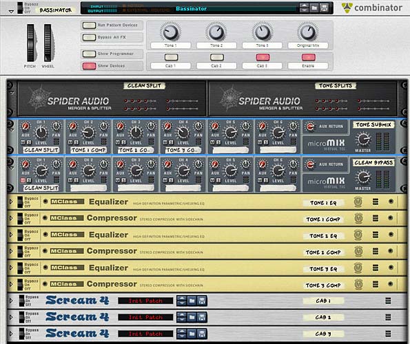
Split an audio signal into multiple parallel audio signals, send them to various effects, and then merge them back together. You control the mix level of all 3 effects and the original signal. As an example, we’ll create a Dynamic Effects processor (Compressors / Equalizers) to apply to your bass sounds.

In this tutorial, I’m going to show you how to split an audio signal into multiple parallel audio signals, send them to various effects, and then merge them back together. You control the mix level of all 3 effects and the original signal. As an example, we’ll create a Dynamic Effects processor (Compressors / Equalizers) to apply to your bass sounds. The Combinator knobs will be used as the basis to sculpt your sounds. Add some additional effects to the buttons and you have yourself some very powerful sound development indeed.

The inspiration for this tutorial came from a procedure I had read about in which the Kick drum is compressed and then the original Kick is mixed back in with this compressed Kick drum to give a beefier sound. So I thought, if you could do this with a Kick drum, how about doing it with other sounds such as a Bass, and then allowing you to mix in not only the original sound, but also different compression schemes. With the Combinator allowing you to utilize 4 knobs, you can actually create 3 different compression/EQ schemes (each tied to their own Rotary on the Combinator), and then tie the original mix to the fourth Rotary. This way, you can have some fun adjusting the balance of all 3 compressions as well as the original to create your final sound. This opens up a huge array of sound possibilities.

Once I show you the method to do this, you’ll be able to parallel process any kind of effect you can create in Reason or Record. For example, we can take 3 variations on a Chorus, and tie each variation to their own Rotary, then have some fun mixing them together. This turns your Combinator into a very flexible Chorus machine.

The project files can be downloaded here: parallel-effects-processing The zip file contains 1 Combinator inside an .rns file and a Combinator template. The .rns file contains the Parallel Processor which we’ll create here. You can use it to process your bass sounds. Different Bass tones and cabinet models are packed inside the Combinator. The template file can be used to start you off creating your own effects. You won’t have to enter any settings in the Combinator’s Modulation Routing, unless you tie some effects to the buttons. Otherwise, have at it building your own Parallel processing effects.

Here’s the basic Combinator setup:

  1. First, Create a new Reason document and then create a 14:2 Mixer. Next, create a sound module, such as a Bass sound. You can find great bass sounds under the Factory Sound Bank (FSB) or you can create one of your own using a Thor, Mal, or Sub. You can even create a sampled Bass sound using the NN-19 or NN-XT. It’s up to you, but since we’re going to create a Combinator effect unit, you’ll need some kind of sound which is to be affected.
  2. Next, create a Combinator under the sound source and in the Combinator hold down shift and create in the following order two Audio Spiders/Mergers, two 6:2 Line Mixers, 3 sets of M-Class Equalizer/M-Class Compressor devices, and 3 Scream devices.
  3. Label the first Audio Spider/ Merger “Clean Split” and label the second Spider/Merger “Tone Splits.” Label the first 6:2 Mixer “Tone Submix” and the second 6:2 mixer “Clean Bypass.” Label each set of EQ/Compressor as follows: Tone EQ 1/Tone Comp 1, Tone EQ 2/Tone Comp 2, and Tone EQ 3/Tone Comp 3. Finally, label the 3 Scream devices “Cab 1,” “Cab 2,” and “Cab 3.” These will be our cabinet emulations. This is how we will refer to each device for the remainder of the tutorial.
  4. Flip the rack around to the back as it’s time to do some serious routing. Note that all the routings below are Left/Right stereo pairs. Move the Audio outputs from the sound device to the Combinator inputs, and then move the Combinator audio outputs to the Main 14:2 Mixer’s Channel 1 inputs. Route the “To Devices” cables from the Combinator to the main inputs on the splitter side of the “Clean Split” Spider device.
  5. Send one of the splits from the “Clean Split” device to Channel 1 input of the “Tone Submix” mixer, another split to Channel 1 of the “Clean Bypass” mixer, and a third split to Main inputs on the splitter side of the “Tone  Splits” Spider device.

    The back of the rack for the Template file.
    The back of the rack for the Template file. I'm jumping ahead a little. But this shows the basic routing before setting up any of the Effect devices.
  6. Send one split from the “Tone Splits” Spider to the “Tone EQ 1” inputs. Send a second split to the “Tone EQ 2” inputs. Send a third split to the “Tone EQ 3” inputs. Then send the audio outputs from each of the EQ devices to the audio inputs of their respective Compressor devices. Then send the outputs of each of the Compressor devices into Channels 2, 3, and 4 of the “Tone Submix” mixer device.
  7. Next, send the Master output of the “Tone Submix” mixer to the input of the “Cab 1” scream device. The “Cab 1” output goes to the “Cab 2” input, the “Cab 2” output goes to the “Cab 3 input,” and finally the “Cab 3” output goes back into the Merge side input of the “Tone Splits” Spider device. Also send the Master output of the “Clean Bypass” mixer device to another merge input on the “Tone Splits” Spider device.
  8. Last but not least, send the Merged output from the “Tone Splits” Spider device to the “From Devices” input on the main Combinator panel. I know this all looks really messy, but sometimes you just have to get in there and get dirty to get what you want out of Reason.
    The back of the rack when finished routing
    The back of the rack when finished routing

    The front of the rack
    The front of the rack
  9. Now let’s flip the rack around to the front and work on the Combinator Modulation Routing section. Click the “Show Programmer” button on the Combinator. Enter the following settings:

    For the “Tone Submix” mixer device:

    Rotary 1 > Channel 2 Level: 0 / 100

    Rotary 2 > Channel 3 Level: 0 / 100

    Rotary 3 > Channel 4 Level: 0 / 100

    Rotary 4 > Channel 1 Level: 0 / 100

    Button 4 > Channel 1 Mute: 1 / 0

    Button 4 > Channel 2 Mute: 1 / 0

    Button 4 > Channel 3 Mute: 1 / 0

    Button 4 > Channel 4 Mute: 1 / 0

    For the “Clean Bypass” mixer device:

    Button 4 > Channel 1 Mute: 0 / 1

    For each the “Cab 1” Scream device (note, each Cab device has the same settings, except Cab 2 is tied to Button 2 and Cab 3 is tied to Button 3):

    Button 1 > Damage On/Off: 0 / 1

    Button 1 > Cut On/Off: 0 / 1

    Button 1 > Body On/Off: 0 / 1

    Combinator Modulation routing for the two Mixers
    Combinator Modulation routing for the two Mixers

Here’s what is happening:

Button 4 is used as a bypass switch. When this button is turned off, the original sound will travel through the Combinator untouched. When Button 4 is turned on, you can use the 4 Rotaries to create a custom mix between all the sets of effects. Rotary 4 is a “special” rotary, in that it allows you to mix the original audio back into the mix. It’s important to note that this original audio is separate from the audio that goes through the Combinator when button 4 is off. Hence the need for two different mixers inside the Combinator. This way you can have the original mix work as though it were just another tone alongside the others, and when you switch back to a “clean” signal, a separate “original audio” is piped through the Combinator.

Buttons 1, 2, and 3 are your different Cabinet emulations. Those with Record are even luckier in that they can add in a few Line 6 Cabinet modeling devices and use those instead of the Scream. But with Reason, you can still get some amazing cabinet models by using the “Body” setting of the Scream unit (in conjunction with a little distortion and EQ cutting if you wish).

Another thing to keep in mind is that the Tones attached to the Rotaries are independent of the Cabinet models. You can dial in Tones without ever having to use the Cabinet models. However, button 4 must be turned on or enabled for you to hear any of the Tones or Cabinet models. In addition, you can have two Cabinet models used in series (note however, that this was not really the intended purpose — my thinking was that you can use each Cab model individually, and not together, but if you want to use them together, go for it).

Now as a final step, you will need to enter individual settings in the Equalizer / Compressor and Scream units. I won’t go into all the settings you can enter, but rather, you should build your own settings within these devices to your taste. However, take a look at my own settings to see what I used for Bass processing. The idea is to create each set of Equalizer/Compressor settings separately. So, for instance, turn rotary 1 all the way right and turn down all other rotaries to zero (fully left). Now listen to your sound source going through the device, and adjust the “Tone EQ 1” and “Tone Comp 1” devices until you hit on a nice bass processing setting.

Next, turn Rotary 1 all the way down and turn Rotary 2 all the way up. Now work on the second set of EQ/Comp devices to get an entirely new bass processing outcome from the devices. Once that’s done, repeat this for the final set of EQ/Comp devices.

Note: If you want to cheat a little bit, select your sound source, and then right-click and select “Create Effect.” Open up the Factory Sound Bank and look under the ALL Effects Patches > Dynamics > Basses folder and open up one of the bass Combinator patches that you like. Now be sure to adjust the settings on the front of this Combinator patch until you find the sound you’re looking for. Then click the “Show Devices” button on the Combinator, and copy/paste the devices from this Bass patch into your parallel processing Combinator. Delete the (now empty) bass Combinator. In the parallel processing Combinator, you will need to do a little routing to set things up as I have (routing into the main inputs of the first device, and routing the outputs from the last device). But once you do, you can then repeat this process two more times choosing different Combinator patches to copy from in the FSB.

Here’s a 2-part video series that expands upon this idea. It doesn’t always come out exactly the way you expect. But that’s the fun of trying out the technique. You may find something worth keeping, and then you can save the Combinator as a patch and use it in your own compositions.

Part 1:

Part 2:

Now for your cabinet models (Scream devices) you would go through the same process.

Note: When working with the Scream devices, in order to balance the volume level between the Original sound / Tones (using Button 4), you will need to raise all the Scream device Master volume settings up to 100. In this way, if you use Button 4 to switch between the Original volume on Rotary 4 and the volume of the clean bypass (being sent to the “Clean Bypass” mixer), the volume levels will match. So first raise all the master levels for all Scream units to 100.

Listen to the bass sound going only through Rotary 1 and with Button 1 enabled. Then enter a proper Cab setting in the “Cab 1” Scream device. When you have something that sounds nice, test it out with the other Tones on the other Rotaries individually. Note that you may need to put a limiter (M Class Compressor) after the Scream device to tame the sound if it gets too crazy.

Why I feel this setup is so powerful

This type of setup can be very flexible and powerful. Instead of using a single effects processor (one EQ and one Compressor) you can create any kind of mix between three different EQ/Compressor setups. Add to that the Cab models and you end up with some very powerful audio processing.

Another reason I feel this setup is powerful is because you end up with a processor that is greater than the sum of its individual parts. It’s also a handy way to store three setups (plus the original mix) in a single Combinator.


So what are your thoughts? Does this open up some new possibilities for you? Have you used this technique before in other areas or with other devices? I’d love to hear your thoughts on this. Thanks for reading. Now go out there and make some amazing music!

Reason Patch A Day Refill

A review of Robb Neumann’s “Reason Patch A Day” Refill, with approximately 500 Patches for Propellerhead Reason. This is one refill you don’t want to miss. Basses, Pads, Effects, Combinators, Synths. It’s all in there. Take a listen for yourself.

If you frequent the various Propellerhead forums and sites, you’ve probably come across Robb Neumann’s “Reason Patch A Day” website. The concept is simple. Robb provides a new patch each day which is produced by him or contributed by others, and he provides a short write-up explaining each one on his blog at http://www.reasonpatchaday.blogspot.com/

Recently, he decided to release the entire 1.5-year collection in a single Refill that anyone can download for a donation. Being a person who runs my own Reason website, I know what goes into maintaining this growing monstrosity. And I know that a few modest donations go a long way. And for 500 patches in a rock-solid refill, that’s well worth it. And that’s what you get.

Some of the great Combinator patches from the refill
Some of the great Combinator patches from the refill. Notice the dedication to Brian Eno in the bottom Combi backdrop. Love it!

There’s Basses, Synths, Rhythm patches, and tons of Effects. If you’re looking for some great new sounds or looking to be inspired and see how one sound designer works his magic, then this is a great refill which you’ll want to have in your collection. Play the video review I put together below to hear some of the sounds and what you can accomplish.

Now keep in mind this only scratches the surface. I could go on and demonstrate many more of his patches, but I think this modest little intro showcases some of the magic you’ll find here.

I think in general the refill focuses on Basses, Synths, Pads and Effects. However, there are also some really nice percussion kits, and a lot of great Yamaha RX one-off samples that you can easily put inside an NN-XT kit.

The only nit-pick I would have is that some of the Combi patches that I opened up were templates where you had to add in your own Redrum kits. I would have liked to have been able to open up those Combis and start rocking out right away. But that’s such a minor nit-pick, it should in no way stop you from downloading this refill right away. You will not be disappointed.

To download the Refill, go to http://www.reasonpatchaday.blogspot.com/ and click the Donate button on the right side navigation bar. Once you enter a paypal donation, Robb will send you an email with a link to download the refill. Simple as that.

I think the cherry on the cake are the Combinator backdrops. There’s some really nice designs in there. I know that’s just a minor thing, but it adds that special touch that is usually lacking in a lot of refills. So this refill gets an extra gold star for that.

So thanks to Robb and thanks to all of you Reason/Record sound designers out there. You guys all give of yourselves so much and so freely that it makes me proud to be considered part of this small little niche community. Keep up the great work!

19 – Spatial-based FX

In a previous tutorial I spoke about how you can create frequency-based FX and divide your FX, sending different delays or phasers or any combination of FX to different frequencies in your mix. This time we’re going to send those same FX to different locations in your mix: Front, Back, Left and Right. This way, we’ll create different FX for 4 different corners of your mix.

In a previous tutorial I spoke about how you can create frequency-based FX and divide your FX, sending different delays or phasers or any combination of FX to different frequencies in your mix. This time we’re going to send those same FX to different locations in your mix: Front, Back, Left and Right. This way, we’ll create different FX for 4 different corners of your mix.

The tutorial files can be downloaded here: 4-corner-spatial-fx This zip file contains 2 Combinators: 4-corner delay FX and 4-corner phaser FX.

Starting of creating the Front and Back sections

First, the video:


  1. First, we’ll start in Reason, and start by opening a new document with all the usual suspects. Create a main mixer, and a sound source (an initialized Thor would do just fine).
  2. Next, create a Combinator under the sound source. Inside the Combinator, hold down shift and create a Unison device (UN-16), Audio Merger/Splitter, 6:2 Line Mixer, Stereo Imager, RV7000, and for our FX device, let’s create a Phaser (PH-90).
  3. Now holding shift down, select the Stereo Imager, RV7000, and PH-90 Phaser, then right click and select “Duplicate Devices and Tracks.”
  4. Routing time (note that all the audio routings we’re going to create here are in Stereo pairs): Flip the rack around, and move the Thor Audio outputs into the Combinator Audio inputs. Send the Combinator outputs to Channel 1 on the main mixer. Send the Combinator To Devices outputs into the Unison inputs. Then send the Unison outputs to the Audio Splitter inputs. Send 1 split into the first Stereo Imager’s inputs (we’ll call this the Front Imager), and the second split into the second Stereo Imager’s inputs (we’ll call this the Back Imager).
  5. Continuing with our routing, send the Imager outputs to the RV7000 Inputs (do this for both front and back imagers). Then send the RV7000 outputs to the Phaser inputs (both front and back). Then send the front and back Phaser outputs to Channels 1 and 3 on the 6:2 line mixer. Finally, send the Mixer’s master output to the “From Devices” inputs on the Combinator.

    The Routings on the back of the rack. Looks complicated, but it's really pretty straightforward.
    The Routings on the back of the rack. Looks complicated, but it's really pretty straightforward.
  6. Flip the rack around to the front. Now it’s time to set up some parameters. On the Front Imager, send both the Lo and Hi bands fully Mono (fully left). On the Back Stereo Imager, send both the Lo and Hi bands fully Wide (fully right).
  7. Open up the Remote Programmer on both the front and back RV7000 Reverbs. The Hall algorithms are the default and these are fine for now. On the front Reverb, reduce the size fully (to 13.2 m) and reduce the Global decay to around 50. Increase the HF Dampening to around 84. On the back Reverb increase the size fully (to 39.6 m) and increase the decay to around 98. Also leave the default HF Dampening at around 28. Finally, decrease the Dry/Wet knob on both reverbs to around 30-40 or thereabouts.
  8. Open up the Combinator’s Programmer, select the 6:2 Line Mixer and enter these settings:

Rotary 1 > Channel 1 Level: 0/85

Rotary 3 > Channel 3 Level: 0/85

Now, the First Rotary controls the Front Mix, and the third Rotary controls the back mix. If you play your sound source through this FX Combinator, you’ll hear the front and back sounds by adjusting the Rotaries. But what makes things more interesting is if you apply different settings to your two Phaser devices. Even some subtle changes to the Frequency and Width parameters can provide a much more rich soundscape which makes even Thor’s initialized patch sound pretty interesting.

You can also leave things as they are, or you can move on and create two more spatial corners in our mix by adding both Left and Right panning. In this way, you create a 4-Corner FX split for Front Left, Front Right, Back Left, and Back Right.

Moving from side to side

Now, for the second part in the Video Series:

So let’s continue on our journey and create a split for left and right.

  1. First thing we’ll have to do is hold the shift key down and create two other phasers; one next to the front phaser and another next to the back phaser. Then select the front RV7000 and holding shift down, create a Spider Audio Merger/Splitter. Do the same for the back by holding down the back RV7000 and creating another Spider Audio Merger/Splitter.
  2. Flip to the back of the rack and let’s set up some new routings. Move the cables from the inputs on both Phasers and move these cables to their respective Spider Splitters (in the main Split). Then send one split to the Front Phaser 1 (let’s call this left) and send another split to the Front Phaser 2 (let’s call this right). Then send the outputs from the two new phasers to Channel 3 and 4 respectively.
  3. Flip to the front of the rack and on the 6:2 Line Mixer set the panning for Channels 1 and 3 to about -22 (left) and Channels 2 and 4 to +22 (right). How far left or right you set the panning is really a matter of taste. With this all set up, the 6:2 Line Mixer will be set up as follows:

    Channel 1: Front Left Phaser

    Channel 2: Front Right Phaser

    Channel 3: Back Left Phaser

    Channel 4: Back Right Phaser

  4. Open up the Combinator Programmer, and assign the 6:2 Line Mixer Channel 2 and Channel 4 to Rotary 2 and 4 respectively as follows:

    Rotary 2 > Channel 2 Level: 0/85

    Rotary 4 > Channel 4 Level: 0/85

  5. Now you can provide labels for all 4 rotaries as follows:

    Rotary 1: Front Left

    Rotary 2: Front Right

    Rotary 3: Back Left

    Rotary 4: Back Right

And there you have it. A 4-corner mix with different FX for each corner. You don’t have to restrict yourself to Phasers. With some ingenuity you can assign any FX to any location, or any combination of FX to any of these 4 locations, and all of those with different parameters too. The only thing left is to adjust the Phasers to have different settings as you see fit.

Here’s a video showing you some of the things you can do to modulate the Phasers:

A few other notes:

  • The reason we set up a Unison device in front of the mix is because this ensures that the signal sent into both the imagers is in Stereo. This is needed for the Stereo Imager to function as it should. It won’t work with a Mono signal. It means that even if you use a Subtractor, for example (which is mono), it can still be sent into the Imagers and the Imagers can work their magic.
  • Using the Width / Mono setting on the Imager bands helps to create the illusion of front and back audio locations. Used in conjunction with the Reverbs, you can create some sophisticated positioning not only with your FX, but also audio of any kind. When you move towards Mono, the sound appears to come from the front of the mix. By widening the bands, the sound becomes more spread out and appears to come from the back.
  • Just as with the Imagers, changing the space size and decays on the Reverbs helps the illusion along. Smaller sizes and shorter decays means a tighter reverb space which appears as though the sound is closer. For the back Reverb, the opposite is in effect. By creating a wider space with a longer tail reverb, you end up with a sound that is pressed further back. Keeping the same algorithm type still binds the two reverb spaces together. However, there’s nothing preventing you from trying to use different algorithms altogether (for example, a Small Space reverb for the front and an Arena reverb for the back).
  • Ever look at those Escher drawings where the staircases keep looping back into themselves? They are impossible pictures. Well, the same can be achieved with sound. You can create some really weird effects by creating an impossible space. Try switching the Reverbs around but keeping the Imagers as they are. The Imagers will tell your ears that the sound should be coming from the front and back, but the reverbs will be telling you the reverse. It can be a disturbing effect. But in the virtual world, you can create these “Impossible” sounds easily. Try that one out.

As always I’d love to hear what you think? Show some love and drop me some feedback or any questions you might have. Until next time, good luck in all your musical endeavors.