82 – Etch Red

This article will introduce you to the Etch Red RE from http://www.fxpansion.com. This RE is a powerful dual multi-mode filter that can be set up in series or parallel. It also comes with a comprehensive built-in and external modulation scheme that is unlike any other in the stock Reason program. Aside from filtering, it is capable of several tricks such as gating, stereo widening, compression, distortion, LFO wobbling, Tremolo, and Vibrato effects. To top it all off, it comes with the ability to Frequency Modulate the filters (either internally via the 2 built-in LFOs, or externally using an incoming audio source). A lot of power for a very affordable Reason device. So let’s take a walk-through and learn a little more about it.

This article will introduce you to the Etch Red RE from FXpansion. This Rack Extension is a powerful dual multi-mode filter that can be set up in series or parallel. It also comes with a comprehensive built-in and external modulation scheme that is unlike any other in the stock Reason program. Aside from filtering, it is capable of several tricks such as gating, stereo widening, compression, distortion, LFO wobbling, Tremolo, and Vibrato effects. To top it all off, it comes with the ability to Frequency Modulate the filters (either internally via the 2 built-in LFOs, or externally using an incoming audio source). A lot of power for a very affordable Reason device. So let’s take a walk-through and learn a little more about it.

Before I get into the nuts and bolts of the device, let me first point you to the PDF User Manual that you can download. This comes straight from the FXpansion site, and it’s a good idea that you have a read before jumping in. There’s a few pitfalls that you want to avoid when working with this Rack Extension, and while it’s a very nicely designed device, there’s still some areas that might cause you to scratch your head.

Next, let me point out the main features of this Rack Extension in a simple video:

It’s all about Source > Destination = Modulation.

The heart of Etch Red is all the wonderful red knobs scattered throughout the upper (Filters) and lower (Sources) section of the device. These knobs allow you to modulate their associated parameters with one or more of the 10 Sources (selected in the Middle section of the device). Indeed you can modulate one parameter with all 10 sources if you like. Where I can see a lot of people getting tripped up is when you start trying to figure out how to modulate one destination with these Multiple Sources. So here’s a step-by-step tutorial to help you get your feet wet with this concept:

  1. Create a Subtractor, Thor, NNXT, or any other sound-generating device in Reason, or else create a new Audio Track and place some audio on this track. My recommendation is to go for a nice Pad sound to start yourself off. Load up a Pad patch from the Factory Sound Bank if you are stumped for creativity.
  2. Create an Etch Red device underneath so that it is auto-routed to the sound device (hint: Etch Red is found in the Creative FX menu if you right-click under the sound device). If all goes well, the sound device’s Left and Right audio goes into the Etch Red device, and then back out to the Mix Channel or Audio Track.
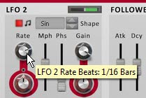
  3. Set the LFO1 Rate to be 1/2 bars and LFO2 Rate to be 1/16 bars. Both are Synced by default. Also adjust their Gain settings to both be set to around 66%. This will remove the harshness of the LFO curve. It’s like a depth or volume setting for the modulation source.
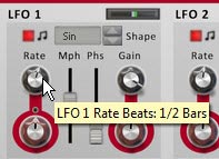
    Setting the LFO1 Rate to 1/2 Bars in the Source (bottom) section of the device
    Setting the LFO1 Rate to 1/2 Bars in the Source (bottom) section of the device

    Setting the LFO2 Rate to 1/16 Bars in the Source (bottom) section of the device
    Setting the LFO2 Rate to 1/16 Bars in the Source (bottom) section of the device
  4. Select a Source from the middle “Modulation Source Selection” section of the device. By default, the LFO1 is selected as a source. You can see this because the little LED within the square icon is yellow. You can also select a source using the drop-down list to the right of all 10 sources. For this example, we’ll use both LFO1 and LFO2 as a source to modulate both Filter Frequencies. Keep LFO1 selected for now. Click the tiny square red LED light just to the bottom right of the LFO1 selector. Turning it off switches the polarity of LFO1 from Unipolar to Bipolar. Leave LFO2 set to Unipolar, which is the default.
    The Modulation Source Selection (middle) area of Etch Red. Note that the LFO1 selector is yellow. You can select a source by pressing these square icons, or by clicking from the drop-down list (both are shown here with a black square border).
    The Modulation Source Selection (middle) area of Etch Red. Note that the LFO1 selector is yellow. You can select a source by pressing these square icons, or by clicking from the drop-down list (both are shown here with a black square border).

    Setting the Polarity of LFO1 to Unipolar by turning the LED off. This ensures the LFO travels both negatively and positively to affect the destination parameter.
    Setting the Polarity of LFO1 to Unipolar by turning the LED off. This ensures the LFO travels both negatively and positively to affect the destination parameter.
  5. Next, switch the Filter 1 Mode to a 4-Pole High Pass Filter (4H) and the Frequency to 6 Hz (fully left). For Filter 2, leave it set to the Low Pass Filter (default), and set the Frequency to around 350 Hz or so. Also set its Resonance (Rez Rotary) to roughly 25%. Note: The Black rotaries change the parameters. The Rotaries encased in Red circles are used to modulate these parameters. So Black changes the parameters outright, while red is used to modulate them negatively (left) or positively (right).
    Setting Filter 1 Mode to a 4-Pole High Pass Filter.
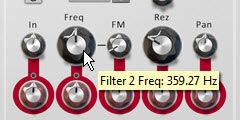
    Setting Filter 1 Mode to a 4-Pole High Pass Filter.

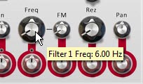
    Setting the Filter 1 Frequency to 6 Hz.
    Setting the Filter 1 Frequency to 6 Hz.

    Setting the Filter 2 Frequency to around 350 Hz and the Resolution (Rez) to about 25%.
    Setting the Filter 2 Frequency to around 350 Hz and the Resolution (Rez) to about 25%.
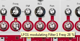
  6. Now we’re set to actually use the sources to modulate the Filters. Using the Red Modulation Rotaries, set the rotaries beneath both filter Frequency parameters to positive 28%. You’ll start to hear the sway of LFO1 affecting the sound as you play the sound device.

    Adjusting the Modulation of the Filter 1 Frequency.
    Adjusting the Modulation of the Filter 1 Frequency.
  7. Select LFO2 by clicking on the square icon in the middle section of the device or using the drop-down at the far right of the 10 Mod Sources. When you switch over to a new Modulation Source, you’ll notice that both filter frequencies’ Modulation Rotaries snap back to their original values (dead center). You’ll also notice that the small LED circle just above these rotaries turn red. This LEDs indicate that there is another source modulating this parameter. Finally, the previous source’s square selector changes from yellow to red (LFO1 in this case). Switch back to LFO1, and these LEDs turn yellow. Switch back to LFO2, the parameters go back to their default and the LEDs turn Red. Yellow = whatever is currently selected in Etch Red. Red = another value is being used to modulate this parameter.

    Note: The one thing that I dislike about working with Etch Red is the fact that when you start creating complex modulations and have several sources modulating a certain Destination, there’s no immediate way to see which sources are modulating the parameter and by how much. You have to click on each source to see how it is affecting all its associated destinations. On the flipside, this does make experimenting with complex modulation assignments quick and you can easily get lost in experimentation. So that’s a plus!

  8. With LFO2 as the selected source, change the Modulation Rotary underneath Filter 2 to a positive 50%. You now have the Frequency for Filter 2 being modulated by both LFO1 and LFO2. That’s pretty much all there is to it.
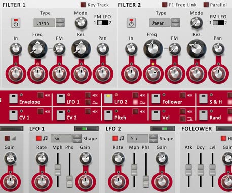
    The Final Etch Red Filter, Mod Source Selection, and Sources sections.
    The Final Etch Red Filter, Mod Source Selection, and Sources sections. Note how LFO2 and the LED just above the Modulation rotary for the Filter 2 Frequency are yellow, indicating LFO 2 is the currently selected source, and Filter 2 Frequency is being modulated by LFO2. On the other hand the LED above the Modulation Rotary for the Filter 1 Frequency parameter is red, indicating it is being modulated by another source (in this case, LFO1).

Note: Of course, you can also modulate a Source’s Rate or Gain settings (at least for the sources listed in the top row of the Modulation Source Selection area) by adjusting the red Modulation Rotaries underneath these parameters (in the bottom section of the device). This can also open up some very complex modulations. You can even use LFO1 to modulate its own Rate and Gain. How trippy.

Getting a little more Advanced

So now that we have a grasp on how Etch Red works, I thought I would delve a little deeper into things by using the Envelope source. In order to get the envelope working, you need to send a Gate input signal into the back of the device. And what better way to trigger the envelope than with a Rex loop’s Gate output. So here’s a little video that shows a few techniques along those lines:

Everyone Loves a Dubstep Bass, right (or am I being sarcastic)?

Here’s a great video put together by FXpansion themselves that goes over the process of creating a Dubstep Bass using their device. It’s a little more advanced, but it’s a great way to showcase how some of the CV modulations can be used on the back of their device. And the sound is just cool, so I had to include it here:

More Tips and Tricks

Here are a few other handy tricks you can try out using Etch Red.

  • Fun with Distortion: Unsync LFO 1 and select it as a mod source. Set its rate to somewhere around 100-600 Hz. Set the output level to -14 dB. Turn up the Drive Mod Rotary slowly. adjust the LFO 1 Rate, Mph, and Drive Types until you find something you like. Great for basses.
  • Tremolo: Select the LFO 1 as a mod source and click the Polarity LED to make it bipolar. Adjust the Level Mod rotary set to a small amount in either direction for Tremolo.effects.
  • More Shapes: Create a Malstrom and from the back send Mod A into Etch Red’s CV 1 input. You can now use Malstrom’s 31 waves as a source to affect any Etch Red Modulation.
  • Dual Filter Gates: Turn off Drive and Filter 2. Set LFO 1 & 2 with “Square” shapes. Ensure the rates are synced, but different for each (ex.: 1/4 & 1/16). Keep the Gain full. Select LFO 1 as a source, and Set Filter 1 to Low Pass (Japan, SVF, or Fatty). Set the Frequency to 6 Hz (full left). Then turn the Frequency Mod Rotary to 100% (full right). Now select LFO 2 as a Source and use it to modulate the same Filter 1 Frequency in the same way (Mod Rotary to 100% – full right). Adjust the depth of both LFOs by adjusting their Gain values.
  • Auto-Panner: Set LFO 1 to Bipolar. Then use LFO 1 as a source adjusting the Pan Mod Rotary for Filter 1. Adjust the LFO 1 settings to taste.
  • FM Audio Fun: Try sending audio from a Loop or a synth into the Filter 1 and/or 2 FM inputs. Then on the front, turn up the FM Rotaries, and adjust the Filter Freq & Res to taste. Noise and Saw Oscillators are great audio inputs too (though you may need to raise their volume). For further manipulation, assign an LFO to modulate the FM amount.
  • Envelopes: To use the Etch Red Envelope, you need to send a CV signal into the Gate CV input on the back. Try sending a matrix Gate CV into the Gate CV input. Now put together a gate pattern in the matrix. Alternately, you can send a Curve CV from the Matrix. Now you can use the Envelope modulation source to modulate any Etch Red Mod Parameters.
  • Key Tracking your Filters: To use the Etch Red “Key Track” feature, create a Sequencer Track for Etch Red. Then copy MIDI data from another Track (some monophonic data works best). Then reduce the Filter Frequency. When you play back the Sequencer, the Filter will follow the MIDI track, and will in essence be following the musical track from which you stole the MIDI data. Or you can just play along on your keyboard to track the Filters.
  • Internal Pitching: Try sending the LFO 1 CV output to the Pitch CV input on the back of Etch Red. Then turn on Key Track on the front, and set up your Filter. Choose a Fatty LP filter for a nice bassy sound. Set Freq to about 185 Hz, Rez to 70%, and set LFO 1 Rate to 34 Hz, Free-running, and Mph to about 77%. Oh yeah, some nice Bass Wobbling.

Hope you enjoy Etch Red as much as I do. It’s capable of quite a lot. If you have any other ideas, tips and tricks, please share them with the class.

73 – Pounding The Pulveriser (Pt. 2)

In this next installment of exploring the Pulveriser, I’ll go a little deeper and see how we can use it for more than just Parallel Compression. We can see how we can use it to warm or destroy a sound, and explore some of the CV / audio routing possibilities to get much more out of the device. And while it’s great on drum sounds and good to beef things up, it can be downright scary when used in a glitch environment. So let’s take a deeper look.

In this next installment of exploring the Pulveriser, I’ll go a little deeper and see how we can use it for more than just Parallel Compression. We can see how we can use it to warm or destroy a sound, and explore some of the CV / audio routing possibilities to get much more out of the device. And while it’s great on drum sounds and good to beef things up, it can be downright scary when used in a glitch environment. So let’s take a deeper look.

You can download the project files here: pulveriser-ideas. This zip file contain a .reason file and separate Combinator files that outline some of the ideas you’ll find in this article.

First, a note about Pulveriser Levels.

If you bypass the filter, and keep the volume level at 100, and the Blend knob fully wet, you’ll notice that the audio source going into the device is higher than it would be if you were to bypass the Pulveriser. If you then turn the Blend knob fully dry, you’ll notice that the signal increases even more. This had me confused, so I went about trying to figure out what level the Pulveriser should be in order to give consistent volume levels for what they would be if they were bypassed. From my tests, I found that a Volume level of 64 when Wet, and a Volume level of 44 when Dry made the device consistent with a bypassed audio source. How helpful is this information? Well, it could help to know in the event you want to have more consistency between the levels going into the Pulveriser and the relationship between the Volume and the Blend knobs. I find myself usually turning the volume down quite a bit in my own patches. But again, it depends on other factors, such as Squash, Dirt, and Filter settings. I just wanted to point out what I found while I was doing my own tests.

In the project files, you’ll see a “Dry-Wet” Combinator that is used to affect an Initialized Thor patch. The first Rotary labeled “True Dry/Wet” was used to crossover the Dry/Wet Blend knob to create consistent volumes with the source audio. It’s just a test file, and whether or not this is of any use to anyone, I’ll let you decide. But it was a good test to find out those equivalent values.

Now let’s have some fun with FM and AM inputs on the back of the Pulveriser

There are two Audio inputs on the back of the Pulveriser that are used to modulate the Filter Frequency with external audio (FM – Frequency Modulation) and the Amplitude Output with external audio (AM – Amplitude Modulation). According to the Reason manual, these inputs accept the rate of the incoming audio signal, so play around with the rate of the incoming audio and this also has an effect on the Filter Frequency and Amplitude.

So here’s an idea. Use two Thor Oscillators that are played via Step Sequencer to affect both the FM and AM in the Pulveriser.

Let’s give our Bass some Wobble (is that a Dubstep Bass Wobble I hear?)

The Pulveriser was not only built to provide Parallel Compression and Dirty up your signal with some distortion. It also is quite capable of wobbling pretty much anything you can think of, and synching or unsynching the wobbled signal. Not only that, but you can spread the wobble across the stereo field if you like with the Spread button. This makes it pretty handy to create Dubstep Bass wobbles without too much trouble. Here’s nifty way you can create a unique Wobble effect for your Bass, or any other audio you care to throw at the Pulveriser.

Here’s a video to outline one of a thousand ways to creatively wobble your bass:

Triggering the Follower via External CV.

You can also “Trigger” the Follower to act via the CV on the back of the device. This means you can use a Matrix Curve CV or Thor Step Sequencer Curve CV to “Gate” the Follower. If you do this, the Follower connection is broken, meaning that the Audio input does not trigger the Follower anymore. Now, your CV connection is doing the work. For example, you could have the Tremor set up to control the Volume (Tremor to Volume knob), and have the Follower control the Filter Frequency (Follower to Frequency knob). In this scenario, the Pulveriser’s incoming volume has no effect on the Follower. Now, the Curve CV is sending both Gate (when the Follower is triggered) and Velocity (the strength of the signal sent to the Follower) into the Pulveriser’s Follower.

Note: The strength or velocity of the signal can be roughly gauged by the red lamp between the Threshold and Attack rotaries. While I love the lamp idea, I would have preferred a dynamic numerical gauge to accompany the lamp (or at least a tooltip readout of the CV velocity value). And for that matter, a numerical readout on the Matrix Curves and Gates. But I digress. . .

Here’s a video to show how to trigger the Follower from an external CV source. In this video, I’m using Thor’s global envelope to trigger the Pulveriser’s Follower:

Some other Assorted things that can be done

You can use the Follower to control any external CV destination. From the back, hook the CV output of the follower to any CV input in Reason. Or send it to a CV input on a Combinator to control any other parameter of any other device inside the same Combinator. This opens up the door to several possibilities because you can shape the Follower’s Threshold, Attack and Release settings to modify its effect on the CV destination.

If you like the Filters in the Pulveriser, you can use the Filter only, without the Squash, Dirt, Follower or Tremor. In this way, the Pulveriser is an advanced Filter device that can warm up your sounds, or carve out your sounds. The nice thing about using the Pulveriser in this way is that it’s one of the easiest filters to insert into your audio flow, and requires no routing knowledge whatsoever. Just insert and start filtering.


What other things are you doing with the Pulveriser that might be of interest to the community? As always, please share your ideas. I hope everyone has a safe and happy holiday season. I probably won’t write any more tutorials until the new year. But you can be sure I’ll be thinking up some new ideas for 2012. Until then, good luck in all your musical endeavors.

72 – Pounding The Pulveriser (Pt. 1)

Now there’s a word with some power behind it: PULVERISE! Let’s pulverise our sound. New in Reason 6 is this wonderful Distortion-Compression-Tremolo-Follower-Filter-Parallel Processor — And oh yeah, it’s got a Lag feature too! Suffice it to say this thing is vintage goodness, and it can do an awful lot to your sound, whether you just want to warm things up a bit, or set your sound to completely self-destruct. Let’s push it to the limit and see where it takes us.

Now there’s a word with some power behind it: PULVERISE! Let’s pulverise our sound. New in Reason 6 is this wonderful Distortion-Compression-Tremolo-Follower-Filter-Parallel Processor — And oh yeah, it’s got a Lag feature too! Suffice it to say this thing is vintage goodness, and it can do an awful lot to your sound, whether you just want to warm things up a bit, or set your sound to completely self-destruct. Let’s push it to the limit and see where it takes us.

This article is going to provide you with an introduction to the device, as well as show you how to use it as a parallel compressor. I’ll get into more tricks with it in part 2. But for right now, I thought we’d first like to get acquainted with all of it’s goodies. So let’s start with a look at all the parameters on the device.

Also don’t forget that my latest Refill, Pureffects, is available with 1,250 effect patches designed specifically with Reason 6 in mind. There’s 200 Pulveriser patches alone, and several Pulveriser-based Combinators with all kinds of interesting routing ideas. Read More about the ReFill.

Explaining the Interface

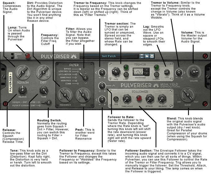
Here’s the front look at the Pulveriser and a brief explanation of what each feature does.

The front panel of the Pulveriser with an explanation of the interface.

Now let’s break down the Pulveriser into it’s Component Sections:

Compression Section

  • Squash: This is another fancy word for Compression. It compresses the audio signal coming into the Pulveriser. So in this respect, it’s kind of like the Compression Ratio of the M Class Compressor. Though it’s probably a different algorithm entirely if I’m reading the Props correctly (maybe Selig can provide charts and comparisons?).
  • Release: Controls the Release of the Squash (compression).

Distortion Section

  • Dirt: This is another fancy word for Distortion. It distorts the signal coming into the Pulveriser. Note that the Dirt algorithm is unlike any other one found in any other Reason device. I have this on very good authority from the Props themselves. So you can think of this as a brand new Scream algorithm if you like. And I must say it’s one of the cleanest distortions I’ve heard in Reason or any other virtual instrument. Definitely one of the highlights of Reason 6.
  • Tone: This controls a low pass filter that is applied to the Dirt. It is outside the realm of the Filter section, so this is not to be confused with any of the Filters found there. This is a separate filter altogether. Practically, it smooths out the Dirt (Distortion), the further left you turn the knob; which may be what you want.

Filter Section

  • Filter: Allows you to select from a variety of built-in Filters. Bypass will bypass the Filter section entirely. The other filters provided are Low Pass 24, Low Pass 12 + Notch, Band Pass, High Pass, and Comb.
  • Frequency: Controls the Filter Cutoff Frequency. Pretty standard for most filters.
  • Peak: This is just another fancy word for Filter Resonance. However, to my ears this Resonance is not as bright as other Resonance settings for other filters in Reason. I may be wrong, or my ears may be shot. But this Resonance algorithm sounds a little more “tame” than the others. But don’t get me wrong, if that is the case, I’m happy about this. It means that we have more choices in Reason on what kind of Filters and Resonance settings to use. More choices = more flexibility.

Tremor Section

The Tremor section can be thought of as an LFO which you can send to various parameters both inside and outside the Pulveriser.

  • Tremor Rate: This controls the Rate of the LFO.
  • Tremor Synch: This controls whether the Tremor is synched to Tempo (when the Sync button is lit) or the Tremor is unsynced/free running (when the Sync button is turned off).
  • Waveform: You can select between 9 different waveforms, as follows: Sine (0), Triangle (1), Square/Pulse (2), Sawtooth (3), Random Square (4), Downward Ramp (5), 3-Step Sawtooth (6), 4-Step Sawtooth (7), and 4-Step Triangle (8).
  • Tremor Spread: This is another fancy way of saying “Pan.” It pans the LFO across the stereo field in a ping-pong kind of way, based on the Rate and LFO waveform.
  • Lag: This is actually yet another filter inside the Pulveriser, however, it’s a filter which is not so much audible, as it is a tool to smooth out the LFO Curve. Obviously if you select a sine wave, it’s already smoothed out, so lag has no effect. But if you select a square wave, for example, the more lag you use (more right you turn the knob), the smoother the corners of the LFO Curve become. So fully right and a square wave would become a Sine wave.

Note: That’s also my biggest beef with the Alligator. For all the greatness it possesses, it doesn’t posses a “lag” knob for the LFOs, which would reduce the pops and clicks I was speaking about in the Alligator tutorial I wrote. And as far as I can tell, there’s no way for you to “add” any lag to the LFO in the Alligator because you can’t, for example, take an LFO from the Pulveriser and use that to affect the LFO of the Alligator.

Oh and by the way, did anyone catch that little note on the back of the Pulveriser? It points you in the direction of how to use the “Lag” feature. However, I don’t see a similar note on Alligator. Too bad.

  • Tremor to Frequency & Tremor to Volume knobs: Here’s how I think of it. When you use the “Tremor to Volume” knob, you are creating Tremolo (change in amplitude over time, or more colloquially, a “Volume Wobble”). Depending where the volume knob is located, this Tremolo effect tremors lower (to the left) or higher (to the right). But it’s more of a Vibrato effect when using the “Tremor to Filter” knob. Because the Tremor creates a “Filter Frequency Vibrato” — think Dubstep Bass Wobble. I honestly don’t know if musical terminology has an alternate name for “Filter Frequency Vibrato” since strictly speaking, “Vibrato” refers to a change in Pitch, not in Filter Frequency.

Follower Section

The Follower is an Envelope Follower that takes the incoming Pulveriser audio and converts it to a CV signal that you can use to modulate all kinds of things both inside the Pulveriser and outside the Pulveriser (via the CV on the back of the Pulveriser – don’t worry, we’ll get to that shortly).

  • Trig: This allows you to manually trigger the Follower section. If you do this, you are no longer using the Audio alone to trigger the Follower. It becomes a manual process (for as long as you hold down “Trig”). Once you let go, if you have any audio going into the Pulveriser, it triggers the Follower to act. Of course, you can disconnect audio from being sent into the Pulveriser and use the Trig button to manually trigger the follower. Nothing is preventing you from doing that. In that case, the Follower is purely manual, with no audio controlling the Follower whatsoever.
  • Threshold: Controls the Threshold of the Follower.
  • Lamp: The Lamp is just a simple red light which turns on while the Follower is triggered. Note that the intensity of the red light shows the level of the Follower. So if the light is dull, the level is low. If the light is intensely red, then the Follower level is high.
  • Attack: Controls the Attack of the Follower.
  • Release: Controls the Release of the Follower.
  • Follower to Rate: The Follower affects the Rate. So if you aren’t using the Tremor to affect either the Filter Frequency or the volume, this knob does nothing. If, however, you are using the Tremor for anything, using this knob will basically send the follower to the Tremor Rate. Depending where the Rate knob is “set” turning this knob left will shift the rate downward (slower rates), and turning this knob right will shift the rate upward (faster rates). So, for example, if the Tremor is affecting your volume, and the Tremor Rate is set to 1/4, turning the knob right means the volume will be “wobbled” at a rate starting at 1/4, but then the wobble will get faster — move at a faster rate — depending on your follower settings. The Follower is kind of like a “rate envelope” (i.e.: it changes the Tremor Rate over time). With the knob set further left of center, the rate still starts at 1/4, but becomes “slower” over time. Personally, this is one of the most interesting knobs on the whole device IMHO.
  • Follower to Frequency: Similar to the “Tremor to Frequency” knob, this knob sends the envelope follower to control the wobble of the Frequency. You can get some really interesting effects when using both Tremor and Follower sent to the Frequency, so its important to play around with both knobs in tandem (though you don’t have to). This is bipolar. Moving the knob more to the left, and the Frequency wobbles below where the Frequency knob is set. Moving the knob more to the right, and the Frequency wobbles above where the Frequency knob is set.

Mix Section

  • Volume: This is the master volume for the Pulveriser. Pretty standard.
  • Blend: This blends the original audio signal with the “Pulverised” audio signal. In this sense, it acts as a Dry/Wet knob. However, when you use this in conjunction with the Squash on your Kick drum, for example, it turns into a Parallel Processor. The nice thing about using the Pulveriser in this way is how easy it is to create create Parallel Compression for your audio, because you only need one device and two knobs to achieve the effect. Of course, you can still use all the other features, such as Dirt, Filtering, Tremor, etc.

Ins and Outs of The Pulveriser: A Look at the Flipside

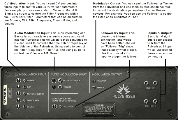
The back of the Pulveriser presents several ways you can modulate the Pulveriser with CV and output the Tremor and Follower to modulate other devices in Reason. Here’s the skinny. . .

An explanation of the connections on the back of the Pulveriser device.

I won’t go into explaining all the uses of the inputs / outputs and CV connections. Instead, the image pretty much says all you need to know. In the next article, I’ll go over some of the uses of these connections, and how you can use them in various Pulveriser techniques. Suffice it to say you have a lot of power on the rear of the device, as I hope you can see from the image above.

Basic Application: Parallel Compression.

So after reading that somewhat elaborate explanation of all the parameters on the Pulveriser, where do you start?

A hint comes in the way I’ve explained things. Notice that each part of the front of the Pulveriser is divided into sections. These sections can be used independently or in tandem to produce results. In addition, the Pulveriser’s sections are also very interdependent; arguably more-so than the other effect devices. So, for example, if you want to Parallel Compress your kick drum you would create your drum sound, and then add the Pulveriser as an insert effect. Bypass the filter section, and use the following:

Squash and Release + Blend = Parallel Compression

Instant Parallel Compression using 3 knobs. It really can’t get much easier than this.

Let’s compare this to how you would traditionally set it up in Reason. To get this setup outside the Pulveriser, you would have to split the output of your drum module and send one split into an M Class Compressor and then out to Mix Channel “1” and then send another split directly to Mix Channel “2.” While you can say that this setup provides for more control over the compression, you could also say that it involves more routing, more time to setup, and more controls to worry about. In our Pulveriser setup, this process is much more efficient and easy to setup and control, at the expense of a slight loss in some of the finer aspects of control (you don’t have Compression Attack, for example, which you DO have with the M Class Compressor setup).

In the Pulveriser, the M Class Compressor would be akin to the Squash and Release knobs, while the two faders used to “blend” the two Mixer channels together would be akin to the (you guessed it) Blend knob.

Here’s a video to show you the comparison:

So which setup do you select? That all depends on what you feel sounds better to you, and it’s important to note that both setups are equally valid. The Pulveriser simply provides you with a convenient way to set up Parallel Compression.


Well that’s it for now. I’m a little worn out from writing all this stuff out. But I’ll come back and continue with the Pulveriser to see some of the cool things you can do with it. Stay tuned. And write me if you think of some really wacky ways it can be used. From my own experiments, I’ve learned you can do everything from enhance and warm up sounds to completely destroy them. Hours of fun, and you won’t hurt anything except maybe your hearing while you experiment. Let me know what you think. And thanks for reading this.

36 – Let’s Talk Compression

Let’s start talking about Compression. In one of my previous tutorials, I showed a way you could use Kong to parallel compress a Kick Drum. So that was one method. But here are a few others that everyone should know about, especially if you’re working on most dance music genres.

Let’s start talking about Compression. In one of my previous tutorials, I showed a way you could use Kong to parallel compress a Kick Drum. So that was one method. But here are a few others that everyone should know about, especially if you’re working on most dance music genres.

Sidechain Compression (aka: “Ducking” or “Gating”)

This is a basic concept that everyone should know. But the twist is that we’ll use Kong, instead of Redrum, to compress a Thor bassline. This way, when the kick drum sounds, the bass is compressed and “ducks out” of the mix. This ensures the Kick drum cuts through the bass in your track.

Compression can also be used for other things as well. It does not have to be confined to a Kick drum and Bassline. You can use any sound source to duck out any other sound source and create a pumping rhythm like this. For instance, you can use a Kick drum to compress your main synth line. This can create some interesting gating effects if used properly.

Parallel Compression

Parallel Compression occurs when you mix a dry sound source together with that same sound source which has been compressed. In this way you get a wider, fatter sound, and you also get the flexibility of controlling the mix between the dry and wet signals. I put together a video to show you how Kong can be used in a Parallel Compression scenario on YouTube. However, why don’t I show you another way you can use a Redrum to parallel process a Kick Drum (a very common usage of this technique), or an entire set of drums (this is a little more unorthodox because you would usually parallel compress one drum at a time, but just to show you that you have options. . . ). Here’s the video:

Frequency-Based Compression

This approach is a little different, but the concept is similar. A lot of times, you might have a specific frequency that you want to “duck” out of the mix. One method you can use is Frequency-based compression, where you compress only a specific frequency in your mix. This is usually used to remove an unwanted sound, and probably the most popular usage for this kind of compression is “de-essing” where those nasty sibilant “S” sounds are removed from vocals. This is really childs play with Reason and the M Class EQ and Compressor devices. Let’s take a look at how it’s done:

As an alternative to using the M Class Eq device, you can use the BV512 Vocoder. In this way, the sound is colored slightly (and moreso if you use the 512 FFT setting), but it’s still a legitimate way that has its own technique. You can see the video of it below. Try it out. You might come to like this method.

Multi-Band Compression

Of course, there’s also something called “Multi-band Compression” which takes the EQ frequency idea to an extreme. This is usually applied to the whole mix at the end of the signal path, before going to the audio outputs. In this way, you set up multiple compressors each affecting a specific range of frequencies. The concept is not entirely difficult, depending on how many compressors you want to set up. For a really great introduction to multi-band compression, I would advise you to check out James Bernard’s week 7 video tutorial on Multi-Band Compression. In addition, James also has a complete multi-band toolkit available as a free download. So go check it out now if you haven’t already!


So that’s it. I’m sure there are other creative ways you can use Compression, but I hope that begins to inspire you to look at compression as a useful dynamic processing tool or even special effect. If you have any comments on this or any other tutorials, please let me know.

9 – Creative ReDrums (Part 1)

I decided to try out some Redrum creativity by taking a standard Redrum patch from the Factory Sound Bank and punching it up. At the same time, I tried to get creative with the Filtering and Routings. A new way to use your Redrum device.

I often get asked and see on the Props forum many complaints that the supplied drum kits are lacking in depth and sound flat. Often this takes the form of slams against the props for providing lacklustre drum kits in the Factory Soundbank. Truth is, the drum sounds can be expanded upon, and if you’re willing to take some time, they can be made to sound much deeper and more punchy. It’s all in what you do with them. The power is all there in front of you, and with the Redrum there’s a lot of flexibility.  

With this in mind, I decided to try out some Redrum creativity and put together a flexible drum kit that takes a basic kit from the props and turns it into something unique . There’s two things I want to accomplish with this tutorial: First: Create a Drum Kit that is more expansive sounding, and Second: Find some creative ways in which the Redrum can be used. So let’s see how far we can take it.  

Before jumping in let me first say that this template is fairly massive. It contains a lot of Thor filters, and as such it can be a little expensive on CPU. If you find it taxing your CPU, you can scale it down (see my notes in the “Where do you go from here” section below), or you can bounce it to an audio track to be put into a Dr. Rex device or as a separate audio track entirely. Second, there’s two main ways I find can bolster the sound of your drums: Compression/Mastering, and Filtering the drums, so those methods will be explored below.  

Download the Project files here: creative-redrums. The project files contain two Combinators inside an rns file. The first Combinator is the Original untouched kit put through the same Matrix sequencing. The second Combinator is the Drums we’re going to create below. Mute/unmute the channels in the mixer to listen to how they sound compared to one another.  

  1. As with all great Reason patches, let’s start by creating a Combinator. Inside the Combinator, create in order, an M Class Compressor, M Class Equilizer, M Class Stereo Imager, M Class Maximizer, 14:2 Mixer, Redrum Drum Machine, Thor Synth, DDL-1, and Spider Audio Merger/Splitter. Then hold Shift down and create a Matrix Pattern Sequencer.
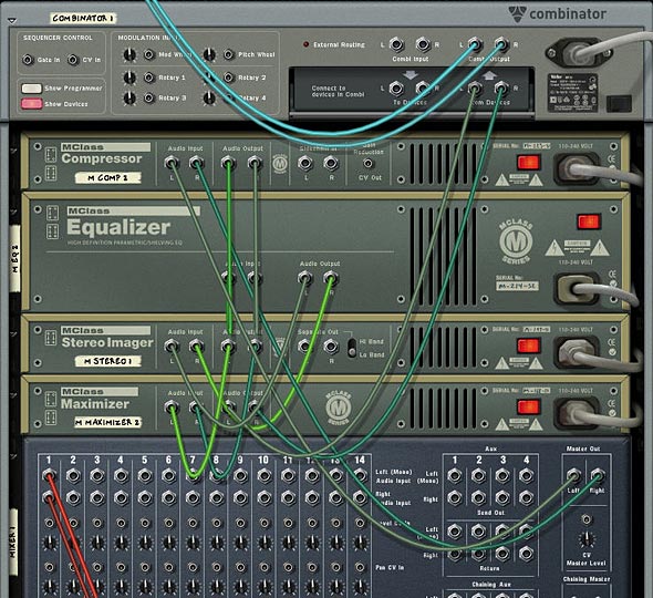
  2. Flip the Rack around and let’s start working on our Routings. First, move the Cables from the Combinator’s “From Devices” ins to the Audio Inputs of the Compressor. Then connect the Audio Outputs from the Maximizer to the “From Devices” inputs on the Combinator. This sets up the main mastering for the Redrum.

    The Mastering setup on the back of the rack
    The Mastering setup on the back of the rack
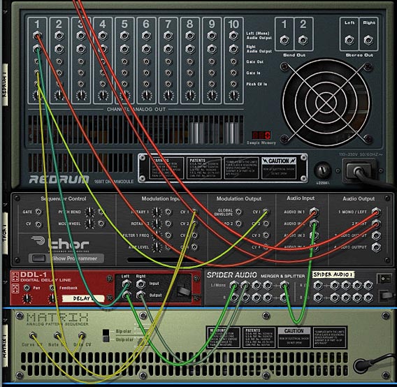
  3. Next, move the DDL 1 Left and Right input cables to the Left and Right Channel 1 on the 14:2 Mixer. At the same time, disconnect the Chaining Aux cables from the 14:2 Mixer. Also, connect the Left output from Channel 1 on the Redrum to the Audio In 1 on the Thor. Then connect the Right output from Channel 1 on the Redrum to the Left input on the DDL-1.
  4. Next, move the Left and Right Audio Inputs from Channel 2 on the Mixer to two Left Audio Inputs on the Merger side of the Spider. Then route a cable from the Left Merged Output to Audio In 2 on Thor. With this setup, you’ll have no delay on the Left audio channel for the drum, while the Right Channel goes through the delay device.
  5. Moving to our CV routing, plumb a CV cable from the Gate CV output of the Matrix to the Gate In on Channel 1 on the Redrum. And plumb a CV cable from the CV 1 Output on the Thor to the Pitch CV In on Channel 1 of the Redrum. Also cable the Note CV output from the Matrix to the CV 1 Input on the Thor, and the Curve CV output from the Matrix to the CV 2 Input on Thor. If this is all starting to get confusing for you, check out the routings in the Combinator file download, or else check out the image below.

    The routings for the Thor Filter, Delay, and Matrix Sequencer
    The routings for the Thor Filter, Delay, and Matrix Sequencer.
  6. Next, let’s flip the rack around and start working on applying settings to the front of the devices. First, click the “Enable Pattern Section” button on the Redrum so that the pattern is disabled. Click the browse button and load a patch (drum kit) into Redrum. I used the Chemical Kit 7 from the Factory Soundbank (under Redrum Drum Kits > Chemical Kits). Now you have a basis from which to work.
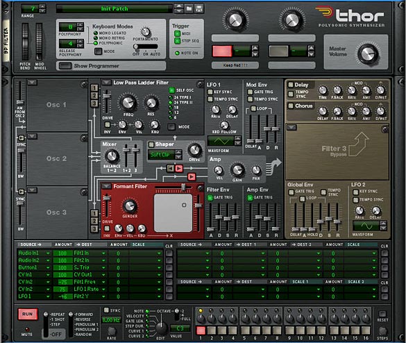
  7. In Thor, we’re going to use multiple filters which will be applied to the Bass Drum (Channel 1 on the Redrum). So the first thing to do is to ensure that the Bass Drum Left and Right channels are routed into Filter 1 and Filter 2. In the Mod Matrix, apply the following settings:

    Audio In1: 100 > Filt1 In  

    Audio In2: 100 > Filt2 In  

    This setup means that the Left (dry) Channel goes through Filter 1, while the Right (delay) Channel goes through Filter 2, and then both are sent in Stereo to be output to the Submixer. 

  8. Next, since Thor is not free running, like the Subtractor, we need to use the step sequencer to keep Thor “On.” To do this, set up a one step long pattern in the sequencer. Turn Button 1 on (so it’s Red) on the top panel of Thor. Then add the following setting into the Mod Matrix:

    Button1: 100 > S. Trig  

    To be honest, since everything will be triggered when you hit the play button, you probably don’t need to setup the above (step 8). But it will ensure that Thor remains on and is running, which will ensure you can use the filters in the Voice section of Thor (the first two filter slots), as well as the Global filter section (Third Filter slot).  If I’m wrong, please feel free to correct me.

  9. Add a Low Pass Filter into Filter slot 1, and a Formant Filter into Filter slot 2. Route both the filters parallel into the Amp section of Thor. Turn off any Oscillators and Oscillator routings, as well as the Mod Envelope and Global Envelope sections. And Then add the rest of the MBRS settings as follows:

    CV In1: 100 > CV Out1 (sends the Note CV data from the Matrix to the CV Pitch in on the Redrum Channel — yes you can send the CV cable directly from the Matrix to the Pitch In on the Redrum, but If you set it up this way, you can then use the Note CV to affect other parameters in Thor, if you wish).  

    CV In2: -75 > Filt1 Freq (sends the Curve CV data from the Matrix to the Filter 1 Frequency).  

    CV In2: 75 > LFO 1 Rate (sends the Curve CV data from the Matrix to the LFO 1 Rate).  

    LFO1: -46 > Filt2 Y (sends the LFO 1 to the Filter 2 – Formant Filter – Y Parameter).  

    Here’s the image which shows the front of the Thor Device and the Filter settings:  

    Thor settings for the main Bass Drum Filtering
    Thor settings for the main Bass Drum Filtering
  10. Next, on the DDL-1, select 4 Steps, and in the Matrix, create a Random pattern. Alternately, you can build your pattern as you play the sequence. The Matrix will trigger the Drum’s Channel 1 gate, and play the pattern you enter. So it can be much easier to build up a drum pattern as you play. Also, as you play, adjust the filter settings in Thor until you come up with your own unique brand of Drums. At the same time, flip the rack and adjust the Pitch In Trim knob on the Redrum Channel 1 to taste.
  11. Now comes the tedious part. Select the Thor, DDL-1, Spider Audio Merger/Splitter, and Matrix. Then right-click and select “Duplicate Devices and Tracks.” Once duplicated, flip the rack around to the back of the devices, and set up the routings into the second Channel of the Redrum and Submix (along with the CV routings, etc.). Do this for each Channel of the Redrum.
  12. Once everything is routed properly, you can start to work on filtering each individual drum channel. Try out different Thor filters, as well as different Matrix patterns (right-clicking and using “Alternate Pattern” works well here, along with shifting the patterns left or right). Also try alternating some of the delay routings from left and right (by reversing the audio inputs on the back of the Thor. Finally, try out different delay steps for each of the delays. There’s lots you can do to fine tune this type of setup.

Combinator Mod Matrix

Going into all the modulations in the Combinator is pretty intense, so instead I’ll let you download the project files and see what’s going on. But a few words about how the Rotaries/Buttons work:  

The Pitch Bend moves all the drum pitches up or down. This can be fun to play with while performing with the drums. The downside is that when the Pitch Bend is static center, so are all the drum pitches. But you can always automate it so that it stays in a non-static, non-centered position.  

The Mod Wheel is tied to a basic drum Reverb which also affects all the drums equally. If you don’t like this Reverb, you can use your own. This way you can apply a little or a lot of Reverb to the overall mix. And then of course there’s nothing saying you can’t add a Reverb or other FX as Send FX on the Submixer. This was a last-minute thought.  

Rotary 1-3: Applies Compression, EQ, and Maximizer Gain to the overall mix. In this way you can master the drums to your liking.  

Rotary 4: Affects the Delay Levels for all drums at once. You can go from no delay (at the far left) to a pretty heavy delay (on the far right).  

Buttons 1-3: Turns on/off the delays for the Bass Drums (1), Snare Drums (2), and High Hats (3).  

Button 4: Turns on/off the Ride by muting it on Channel 10 of the Submixer.  

Where do you go from here?

  • Add different variations and drum patterns (fills and rolls) in the Matrix pattern sections. Then create sequencer tracks for all the Matrixes. In this way you can play the patterns for each of the drums in their own separate tracks on the sequencer, and they are all pattern-based. This makes creating several variations very easy not only to explore, but also to apply in your song.
  • If things are a little too chaotic having all 10 drums running at once, simply mute some of them in the Drum Submixer, so let’s say you have a Bass Drum, Snare, and Hi Hat instead of an all-on cacophony of drums.
  • At the same time, if the CPU load is a little too much, try minimizing the number of filters used, and instead run each drum channel through only one filter, instead of two. Or delete the drums you aren’t using, along with their associated Thor/Delay/Splitter/Matrix.
  • Once you have this template built (and you already have mine done for you), you can add different drum kits into Redrum, and adjust settings for your filters, mastering, etc. One thing that helps is to work on the drums in a build-them-up-as-you-go way. So first do the Bass Drum, then mute the bass drum and go on to the Snare, then unmute and see if they work together. Once they do, move on to the next drum.

And no more than a few days after I posted this article, Matt Piper posted a great little youtube tutorial on how to process your drums through a BV512 Vocoder. You have to check it out. It sounds awesome. Great inspiration for those that want another way to beef up your drum kits: propellerhead-record-reason-vocoding-with-drums

So let me know what you think of this setup. Do you know of some great methods for getting more out of the drum sounds provided in the Factory Soundbank? Do you have any creative drumming techniques. Please feel free to share them. I’d love to see what can be done to boost the supplied drums and learn some new creative ways to ReDrum the kits. Good luck in your Reason projects!