12 – Crossfading Mals & Filters

Since Ed’s Thor Shaper article, I’ve been thinking about how to use this information in real-world examples. One idea is to crossfade the Grain Samples in the Malstrom and another idea is to crossfade all 4 Thor filters to affect one sound source. Lots of fun!

Since Ed’s Thor Shaper article, I’ve been thinking about how to use this information in real-world examples. One thought came from a post I saw on the Props forum. Basically, the issue was that you can’t assign the Malstrom Grains to a Combinator Rotary to effectively switch between the 80+ Grain Samples. It’s pretty easy to assign and switch between Modulator waveforms using a Rotary, but not the actual samples in the Malstrom. So this got me thinking of how you could go about switching between these Samples. And truth be told, there’s probably some really obscure way to do it which uses Thor and some heavy CV connections. But here is something that might just inspire you and be the next best thing.

You can download the project zip file here: crossfading-malstroms-and-filters. This file contains 2 rns files with the Combinator setups explained below. One is a 16-Malstrom crossfader, and the other is a 4-way Thor filter crossfader. I would recommend you download them and open them up as you read. It will make things a little easier that way.

Crossfading 16 Malstrom Grain Samples

In this setup, I’m using 16 Malstrom devices and each device is sent to a Mixer Channel in two 14:2 Mixers. The CV from the various Thors are sent to the Mixer Levels, where the level trim knobs are pushed all the way right, and the Mixer channel Levels are set to zero. If you haven’t already seen Ed’s interesting and enlightening tutorial on the subject, you should read it here: Ed’s Thor Shaper Tutorial. It goes through using the Sine Wave Shaper in Thor to create a 4-way Crossfader. In this way, you can cross-fade between 4 different Malstroms. Each Malstrom’s Oscillator A is set to a different Sample.

Since you have 4 Rotaries, each Rotary is set to 4 Malstrom devices. Giving you a total of 16 different Oscillators. Also, since one or more oscillators will be playing at any one given time, I’ve set up each button on the Combinator to mute the specific series of Oscillators. Button/Rotary 1 affects the first group of 4 (Malstroms 1-4), Button/Rotary 2 affects the second group of 4 (Malstroms 5-8), and so on. Only 10 Malstroms should be applied to a single Mixer because you can only map 10 parameters from any one device to the Combinator, and you need all 10 channel mutes mapped to the various Combinator buttons.

To take this a step further, you could create 6 Combinators, which together would contain the full 82 Oscillator Samples used by the Malstrom. Then you could crossfade between any oscillator you like. The sweet spots for each of the rotaries are as follows:

0 = Oscillator 1 Full Level

42 = Oscillator 2 Full Level

85 = Oscillator 3 Full Level

127 = Oscillator 4 Full Level

Any integer between those values will provide a crossfade between the two Oscillators on either side of the value. This can be seen as a downside or an upside. If you want a pure switch between Oscillator 2 and 4 for example, you can automate the Rotary to go straight from 40 to 85 in your sequencer using a Rotary automation lane. In this sense, you can use the Rotary as a 4-way button switcher between each Oscillator.

On the downside, you couldn’t effectively crossfade between Oscillator 2 and Oscillator 6 (on Rotary 2) the way the current Combinator is set up. But if you Reorganize the way the buttons mute, you could effectively do this. I’m open to anyone who has any other suggestions on how this could be achieved. Another downside is that since a different Malstrom is used for each Oscillator, you’ll have to tweak the settings on each Malstrom to get exactly the sound you want. If you want to keep everything consistent between all Malstroms, you’ll have to do it through automation (the easiest way I think). Simply automate one parameter on the first Malstrom in the sequencer, and copy that automation clip into every other Malstrom’s automation lane. It’s a bit of a pain, but it will keep all Malstroms in line, if that’s what you want.

On the upside, since there are 16 different Malstroms, you can fine tune the sound of each of them separately. If you have all the mutes off, you can effectively crossfade between 4-8 Malstrom sounds/devices at once just by shifting the Rotaries around. This adds some very interesting Sound Layering potential.

As it stands, the first 16 Oscillators from the Malstrom are applied to the 4 Rotaries on the Combinator. As I said, you could build up a stack of 6 Combinators to include all the Malstrom Oscillators. In this way you can build up various sounds and switch between the various Oscillators. Does this help anyone out?

Crossfading all 4 Thor Filters, and then some. . .

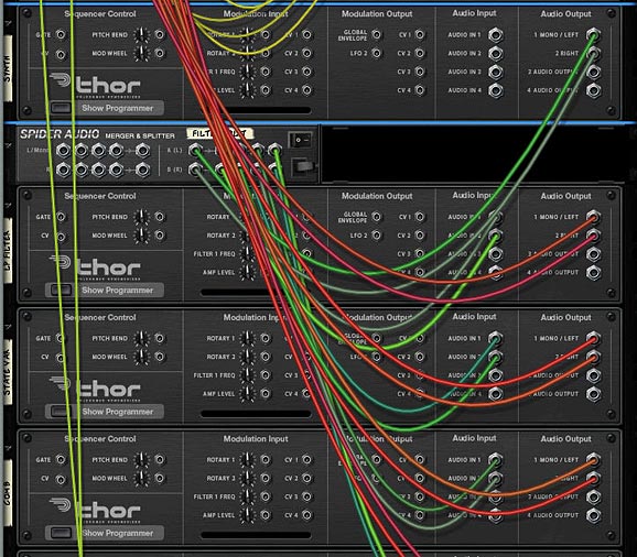
Next, let’s take a look at how we can crossfade all of Thor’s filters to affect one synth sound. In this case, it’s fairly simple to set up. First, create a Combinator, and set up Ed’s 3 Sine Shaper Thor’s to handle the CV like the previous example (along with a 14:2 Mixer). Then create a Thor and load up a synth sound. Start off with something simple so that you can really hear the different filters affecting the sound. Then create a Spider Audio CV Merger / Splitter, and send the synth’s Left and Right Audio Outputs to the splitter’s inputs. Create 4 Thors underneath the splitter and send each of the 4 splits to these respective Thor’s Audio Inputs 1 and 2. Finally, send the 4 Thor’s Left and Right Audio Outputs to the first four 14:2 Mixer channels.
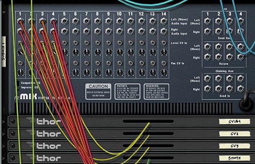
The setup with The Sine Shaper CV and Audio outputs from Thor into the Mixer
The Thor Synth Audio being split and sent through the 4 Thor Filters

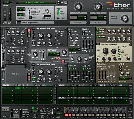
On the front of the Rack, add a Low Pass Ladder Filter in the first Thor’s Filter 3 Slot. The settings for this filter are shown in the image below. In addition, add the following into the Modulation Bus Routing System (MBRS):

Audio In1: 100 > Filt3 L.In

Audio In2: 100 > Filt3 R.In
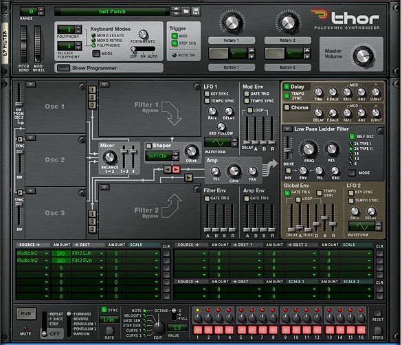
The Low Pass Ladder Thor Filter settings on the front Panel

Enter the same settings in the other 3 Thors, but with different filters, so you have the State Variable filter in Thor 2, Comb filter in Thor 3, and Formant filter in Thor 4. While you’re at it, play around with the Global ADSR envelope so that it sounds to your liking for the 4 different filters. It’s ok if these settings are different for each filter. This will just make your sound more interesting. One thing I kept the same across all 4 Thor Filters is the FX section (Delay and Chorus). This way, when the filters are transitioned, the FX remain similar across the board.

Now let’s turn to our Combinator section and do some serious routings in the Mod Matrix. Here’s the settings you will need for each of the Thor Filters (they are the same for all 4, but must be applied to all 4):

Rotary 1 is reserved for the Filter Crossfade, so I’m not going to go over it here. You can see it in the Project File rns.

Rotary 2 > Filter 3 Freq: 0 / 127

Rotary 3 > Filter 3 Res: 0 / 127

Rotary 4 > Filter 3 Global Env Amount: 0 / 127

Button 1 > Delay On: 0 / 1

Button 2 > Delay Sync: 0 / 1

Button 3 > Chorus On: 0 / 1

Button 4 > Filter 3 Global Env Invert: 0 / 1

Mod.W > Filter 3 Drive: 50 / 127

The Combinator Mod Bus Routing settings for each of the Filters

Now, what’s happening is that the Mod Wheel controls the drive amount on each of the Filters, While Rotary 1 cross-fades all the filters. This is the main Rotary, and it has the same sweet spots as the previous Malstrom patch. Rotary 2 and 3 control the Frequency and Resonance of the filters, and Rotary 4 adjusts the Envelope of the filter. Button 4 inverts this envelope. The remaining buttons are left for the Delay, Delay Sync and Chorus. Since all the parameters are the same for all the filters, they all shift together. This can be a positive or a negative. You can’t individually set the filters, but at least they sound pretty good when transitioned. Depending on your ADSR settings for the Global Filter, the Envelope Rotary and Envelope Inversion Button may be different for each filter. But as I said before, this can add some nice variety to the sound.

Use this Combinator as a template for your own sounds. All you have to do is add your own patch into the Thor “Synth” or change the Thor “Synth” to any other Synth or Sampler device if you like. Then you’re in filter crossfading heaven.

A huge thanks to Ed for being the inspiration for these patches. Please let me know what you think and if you can think of any other applications that this crossfading technique can have, by all means share it with us. Until next time, have fun with these.

11 – Creative ReDrums (Part 3)

In this Tutorial, I’m going to show you a few other innovative things you can do with a Redrum device and a little imagination. First, we’ll build upon the drum kit we created in Part 2, and then branch out to show how you can chain your drums together and layer them to give a richer thicker sound. Finally, I’ll point out a few other quick and easy tricks, just to get your inspiration flowing.

In the first Part of this series, I showed you how to punch up your factory soundbank drums, and in the second, I showed you how you can create your own synth drum kit and trigger each drum via the Redrum device. In this Tutorial, I’m going to show you a few other innovative things you can do with a Redrum device and a little imagination. First, we’ll build upon the drum kit we created in Part 2, and then branch out to show how you can chain your drums together and layer them to give a richer thicker sound. Finally, I’ll point out a few other quick and easy tricks, just to get your inspiration flowing.

You can download the project files here: creative-redrums-3 The file contains two rns files with each of the Combinator setups outlined below.

Expanding on the “Electro Drums Combinator”

If you haven’t already, read Part 2 in the Redrum tutorials. After you’ve done that, you can start by downloading the Combinator I created or you can start with a Combinator that you’ve created yourself, because I know you want to stamp your name on your own sounds right?

  1. If you’ve done everything according to spec, you’ll have a pretty expansive drum kit which is filtered through a Vocoder. Now we’re going to change a few of the routings and Combinator mod matrix settings in order to put a new spin on that drum setup.
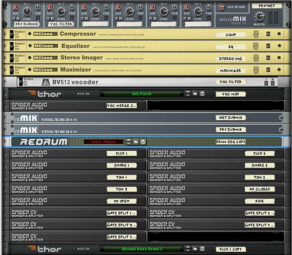
  2. Open up the Combinator and create a 6:2 Line Mixer at the top of the stack. Reroute the Vocoder Carrier outputs to the second channel of the Line Mixer. This is going to be our “Wet” signal. At the same time, connect the Left and Right Audio Out cables from the Line Mixer, and feed them into the Compressor’s Left and Right Audio inputs. Then connect the Left and Right Audio outputs from the Maximizer into the Left and Right Audio inputs on the Combinator (From Devices). So the signal path goes from the dry signal through the Vocoder, then into the Main Line Mixer, then into the Mastering devices, and finally out of the Combinator.
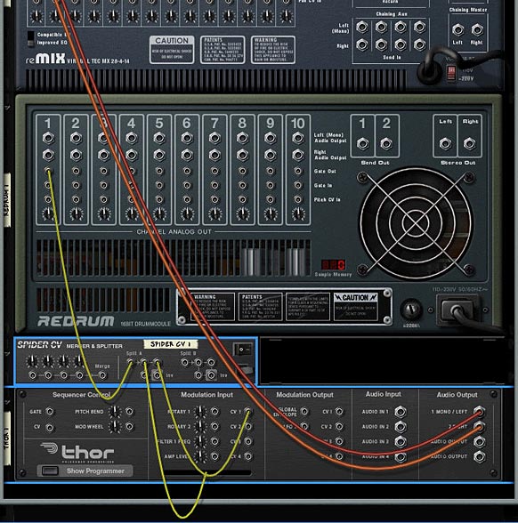
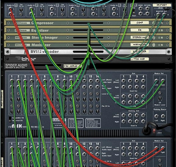
  3. Next, we’re going to add a “Dry” drum submix which can in turn be mixed in with the wet submix. To do this and also to have full control, we’ll need to create a whole new secondary mix. The easiest way to do this is to duplicate the 14:2 Drum Submixer, and holding Shift down, create 10 Audio Merger/Splitters underneath. Flip the rack around and connect each of the Synth Drum outputs (the Thors) into the Splitter inputs. Then use one split to go to the Wet Drum Submix channels, and a second split to go to the Dry submix channels. This is a bit of a process but it’s an important one as you’ll see in a minute.

    Routings from the back of the two Submixers
    Routings from the back of the two Submixers
  4. Now route the entire “Dry” Submix (Left and Right outputs) to the first channel in the main Line Mixer (Left and Right inputs). Flip the rack around and click the “Show Programmer” button on the Combinator. In the Modulation Matrix, remove the “Master Level” settings we previously mapped to Rotary 4. Instead, select the “Main Line Mixer” on the left, and enter the following settings:

    Rotary 4 > Channel 1 Level: 0 / 127

  5. Now when Rotary 4 is fully left, the signal is fully wet. When the Rotary is fully right, the dry signal is mixed in with the wet signal. Furthermore, if you want to fine-tune the levels of either the Wet or the Dry drums individually, you can set that up using the levels on either submixer, giving you total control over both your wet and dry drums’ attenuation. If you want to automate the process, create a sequencer track for both the Dry and Wet Submixer and go ahead and automate the levels to your heart’s content.

    Rack devices in the Combinator above the main synth drums
    Rack devices in the Combinator above the main synth drums

Note: In the Combinator I created inside the Project files, I also added an “Instant Glitch” and “Bass Boost” button which can be used to give the drums a completely new feel. I wouldn’t use them together, but separately they can open up a whole new way to play this patch. Also, there’s some other modifications I made to the original drums. I added a Vocoder Bypass switch on button 4, so if you are bypassing the Vocoder, there’s no need to mix in the dry signal, as the signal is already completely dry. So if bypassing the Vocoder, keep Rotary 4 fully left. Otherwise you’ll be doubling the dry signal which may not be desired. And lastly, I mapped Rotary 1 to the Stereo Width, so turn it fully left to create a pseudo-mono effect, and fully right to widen up the stereo field.

The front Combinator Controls

Chaining 2 or More Redrums Together

Another thing you can do with Redrums that can amplify and expand your drum programming is to Layer your drums by chaining them together. Whether you use Redrum patches for your drum sounds, or create a sample-based drum kit and have the Redrums trigger the synths, you can still create layered drum Combinators very easily. Here’s one method to do this.

  1. First create a Combinator and holding Shift down, create the following devices in sequence: M Class Compressor, M Class Equilizer, M Class Stereo Imager, M Class Maximizer, RV 7000 Reverb, 14:2 Line Mixer, 3 Redrums, and 2 DDL-1 Delay units.
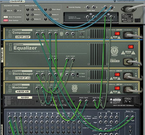
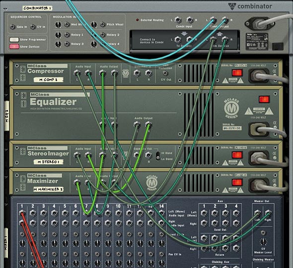
  2. Flip to the back of the rack, and Connect the Left and Right Mixer outputs to the Compressor’s Left and Right Inputs. Then chain the Compressor to the Equilizer to the Stereo Imager to the Maximizer to the RV 7000 and then out to the Left and Right Combinator inputs (From Devices). That essentially sets up the Drum Mastering.

    Routing for the Mastering in the Combinator
    Routing for the Mastering in the Combinator
  3. Connect the Left and Right Outputs from the first Redrum to the first channel on the Mixer. Connect the second Redrum’s Left and Right Output through the first DDL-1 unit and then to the second channnel on the Mixer. Connect the third Redrum’s Left and Right Outputs through the second DDL-1 unit and then to the third channel on the Mixer. This sets up our Redrum Audio channels.
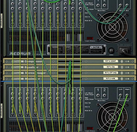
  4. Lastly, send the Gate Out CV for the first Redrum’s first channel to the Gate In CV on the second Redrum’s first channel. Then send the Gate Out CV on the Second Redrum’s first channel to the Gate In CV on the third Redrum’s first channel. Repeat this process for all 10 Redrums’ channels. This way, the first Redrum acts as the “Master” Gate triggering the other two “Slave” Redrums in Parallel (actually this is in series, but the effect is that all three Redrums trigger at exactly the same time, which is why we’ve inserted a Delay unit between the last two Redrums and the Mixer).

    CV routing between the "Master" (Gate Out) and "Slave" (Gate In) Redrum
    CV routing between the "Master" (Gate Out) and "Slave" (Gate In) Redrum
  5. Flip the rack around to the front. Bypass all the M Class devices as well as the Reverb and Delay devices for now. Add patches into the three Redrum devices so that you have different drum kits in all three. Then disable the pattern section on the two Redrum Slaves (last two Redrums). Add a pattern into the Redrum Master (the first Redrum — simply select the device, and click Ctrl+R to get a random pattern entered). Then press the Play button and you’ll hear all three Drum kits working the same pattern at the same time. This is your basic setup.
  6. Next, turn On the Delay units and enter some step sequence that sounds good for the second and third drum kits. This is a matter of taste, but if you look at my Combinator file, you’ll see I have the second Redrum’s delay set to 3 steps and the third Redrum set to 6 steps. I also adjusted the levels and Panning of all three drum kits in the Mixer so that it didn’t shatter my speakers and start giving me that beautifully annoying red clip light (Note that I also added a Scream 4 unit between the third drum kit and its associated Delay line. That’s because the drums from the third drum kit sounded a little lacking). By delaying two of the three drum kits you end up with a much fuller sound. However, this can be a bit of overkill as well. If you like, try tuning the Dry/Wet knobs on the delays so that the delay is a little more subtle. Again, it’s all a matter of personal taste.
  7. Finally, adjust your Compression, EQ, Stereo Imaging, and Maximizing using the M Class Devices. What’s more, you should experiment by using separate M-Class devices for each of the Redrum kits and adjust them independantly. In this way, you can have a greater degree of control over the final sound. In fact, if you want to go all out, you should create four sets of M Class devices; 1 for each of the drum kits, and one for an overall mixdown of the three drums together. This can help to really bring the drum mixes together.

The whole idea here is to choose drum kits that work well together and don’t clash. They should compliment each other. Some ways to ensure they are complimentary is to choose drum patches in the same or similar vein (all Dub kits or all Electronic kits). Another way is to EQ each drum kit so that it has its own place in terms of frequency. A third way is to pan them and mix their stereo width so that they also have their own space within the stereo field. This, of course is beyond the scope of the tutorial, but it’s all a matter of your own personal taste. Keep experimenting!

If you look at the Combinator Mod Matrix, you’ll see that I’ve mapped the second rotary to the pitch of all 30 drums in the 3 Redrum devices. This is a great way to quickly change the pitch of all the drums in the Combinator. The downside is that since you use 10 routings per device in the Mod Matrix, you lose the ability to map anything else from the Redrum devices to the Combinator. So I’ve opted to show you how to map the pitch to the rotary instead of mapping the pattern sequencer to a Rotary control. However, if you want to automate the Pattern Sequencer from the first Redrum, simply create a sequencer track for the Redrum, then automate your patterns directly in Reason or Record’s main sequencer. A few more clicks, but it’s still fairly easy to program.

Where do you go from here?

This is definitely not the end-all-be-all when it comes to the Redrum. There’s a lot more you can explore, such as mapping some of the other parameters to the Rotaries, for example the drum level knobs, or the main Resolution knob. You can also automate pretty much every element of the Redrums in the main Sequencer. In addition, you can layer your own synth sounds on top of each other to create some pretty massive synth drum kits. Hopefully this at least gives you a few new ideas when it comes to programming your drums. I know after 3 tutorials on the subject I’m done working on the Redrum for a while. Time to get back to working on some synths again.

So do you find these setups useful? Do you have any setups that you’d like to share? I’d love to hear about them. Feel free to comment and let me know. And thanks for taking the time to read these tutorials. Your feedback and comments are very much appreciated.

Monochrome Wiring

The ultimate in Combinator Backdrop design. This update expands on the previous “Psychedelic Leaves” backdrop design, providing 1 new Plate design and Scale option, as well as providing “+/-” indicators. All wrapped in a brand new “Monochrome Wiring” Background, with new colors. Use as is, or add in your own designs.

Download the Backdrop File (PSD – Photoshop) here: monochrome-wiring
Requirements: Photoshop CS 1. and above.

Description: The ultimate in Combinator Backdrop design. This one file extends the functionality of the original Reason template and takes it to new levels of flexibility. This update provides new design options and expands on the previous “Psychedelic Leaves” backdrop design even further. See the features (outlined below the 2 sample images). Note: The images below are sized down (i.e., lower quality). I assure you they look much better when applied to your Combinator.

monochrome wiring Combi backdrop with Semi Glow Plate design
Semi Glow Plate design with new Arrow Scales and +/- indicators
Monochrome Wiring Combi Backdrop design with Rivet Plate design
Outer Plate and Rivets Design with Bipolar Arrow Scales and new +/- indicators

Features:

All aspects of the design can be customized since everything is on separate layers. The following can be customized for all elements (both text and image elements):

  • Opacity of the Layer
  • Use of Layer Blend Modes on every layer
  • Color
  • Layer Styles
  • Hue/Saturation and other Adjustment Layers

Six types of Rotary Scales can be selected (The new Arrow Scales are shown in the first backdrop design image above). Note also that there are separate plus (+) / minus (-) indicators, which can be optionally selected if you like. They work in tandem with the Hash, Arrow and Point Scales and are shown in both of the images above. The six Scale styles are:

  1. Hash Scales (Reason’s default)
  2. Point Scales
  3. Arrow Scales (*new*)
  4. Bipolar Arrow Scales
  5. Ramp Scales
  6. Bipolar Ramp Scales
  7. Plus (+) / Minus (-) indicators (*new*)

Four plate designs (The new Semi Glow Plate design is shown in the first image above):

  1. Outer Plate with Rivets
  2. Inner Plate with Inner drop shadow and adjustable gradient overlay
  3. Separate Glow Plate design
  4. Semi Glow Plate design (*new*)

This time, I removed the Device Names that were in the previous backdrop file, and instead created a “Text Layers” folder set with both the Logo Name and Device Name layers included. This way, it’s easier to just change the name to anything you like, rather than sifting through a bunch of text layers to find the name you want. The Device Name is placed in the top-right section of the Combinator, so it is visible even when the Combinator is minimized. Note that you can also adjust the color, opacity, text, layer style, etc. of each text layer separately

Top and Bottom of the Background is divided into separate layers so you can fill the top and bottom with different designs, fill colors, images, etc. The top portion has transparency locked so you won’t accidentally fill in the bottom portion. So it’s as safe as can be.

The bottom portion of the background has a simple gradient fill layer in which you can adjust how much gradient (lighting) to apply to the design (or turn it off by hiding it if you wish).


Basically, you have a wide degree of control over the look and feel of the basic design. Let me know what you think, and let me know if there is a way I can add to this or make further adjustments. Right now, I’ve made it very flexible. But I’m always looking at ways I can expand on this design and future designs.

Ed’s Thor Shaper Tutorial

I’m always amazed with EditEd4TV’s ability to analyze what should be a simple signal path. He literally blows my mind when it comes to this technical stuff. And I find myself reading it about 5 times before some part of it actually sinks in. And of course the real fun comes in figuring out just “what” musically you can do with this information. So not to disappoint, Ed is back with a great tutorial on the inner workings of Thor’s Shaper feature, and more specifically the “Sine” wave inside the shaper. If you feel brave enough, my young paduan learners, then venture forward where quite honestly no man has gone before. . .

I’m always amazed with EditEd4TV’s ability to analyze what should be a simple signal path. He literally blows my mind when it comes to this technical stuff. And I find myself reading it about 5 times before some part of it actually sinks in. And of course the real fun comes in figuring out just “what” musically you can do with this information. So not to disappoint, Ed is back with a great tutorial on the inner workings of Thor’s Shaper feature, and more specifically the “Sine” wave inside the shaper. If you feel brave enough, my young paduan learners, then venture forward where quite honestly no man has gone before. . .

Download the project files here: EditEd4TV_ThorShaperFiles. They contain an Excel spreadsheet with the settings for various sine wave values/positions, as well as Ed’s 4 source cross-fader which was designed using the Shaper’s Sine wave. Quite a brilliant design idea.


Thor’s Shaper can produce a number of interesting distortion effects when processing an audio signal from any of the three oscillator slots, but one of the more arcane features of the shaper is the processing of CV data. In this setup I’m routing the mod wheel data, 0-127, into Filter 1, which is in bypass mode (no filter), which is then routed into the Shaper, set in the sine wave preset. So that you don’t bypass the learning here, I’m not providing the patch, as it’s better to get your hands dirty and learn the hard way, so let’s make this specific patch before moving on:

Processing CV data through Thor’s Shaper

  1. First, create a Thor device and initialize the preset if necessary.
  2. Next, set filter slot 1 to bypass.
  3. Deactivate oscillator 1 routing to filter 1, and activate it for filter 2.
  4. Activate the routing button to send filter 2 to the amp (it’s directly below the Shaper’s Drive knob).
  5. At this point, if you set the Step Sequencer to Repeat mode, and press the Run button, you should hear a basic repeating pulse coming from oscillator 1. If you don’t hear this, go back and check your settings before moving forward.
  6. Next, in the Step Sequencer, move the Steps knob on the far right so that we have only 1 step. For this single step, set the gate length from 75% to 100%. At this point, if you press the Run button you should hear a single pulse that drops in volume. Change the oscillator type from sawtooth to a sine wave for a more pleasant tone, and raise the amp envelope sustain level from -21.8 dB (default) to full 0.0 dB. At this point you should hear a steady sine wave tone. Again, if you don’t hear this, go back and check your settings before moving forward.
  7. In the Modulation Bus Routing Section, make the following assignment:

    Source -> Amount -> Destination -> Amount -> Scale

    Mod Wheel -> 100 -> Oscillator 1 pitch

  8. At this stage, if you raise the mod wheel you should hear the pitch rise and fall as you move the mod wheel – this is direct control with essentially linear control/results. Change this amount value to 0 for the time being.
  9. Now activate the Shaper, change the mode to Sine, and in the Modulation Bus Routing Section, make the following assignments:

    Source -> Amount -> Destination -> Amount -> Scale

    Mod Wheel -> 100 -> Filter 1 Audio Input

    Shaper -> 100 -> Oscillator 1 pitch

  10. At this stage, if you raise the mod wheel you should hear the pitch first rise, but then suddenly begin to fall. This is the sine wave of the Shaper controlling oscillator pitch. At the default of 37, you’re hearing just a portion of what’s available in this shaper setting. For a nearly perfect full sine wave cycle, set the Shaper Drive value to 50. If you listen carefully to the results, you’ll hear that with the Mod Wheel at full 127, the pitch is slightly higher than with the Mod Wheel at 0. To verify that things are off a bit, create an Analog Oscillator in oscillator slot 2, set the type to sine wave, and engage the routing button to filter 2 for oscillator 2. With the Mod Wheel at 0, you’ll hear the two oscillators in perfect sync, but with the Mod Wheel at 127, they’re off a bit. To trim this, in the Modulation Bus Routing Section, modify the previous assignment to this:

    Source -> Amount -> Destination -> Amount -> Scale

    Mod Wheel -> 100 -> Filter 1 Audio Input -> 2 -> Rotary 2

  11. You should hear Oscillator 1 pitch drop a bit. Now turn up Rotary 2 and you’ll hear the pitch rise to meet up with Oscillator 2, which is unaffected by the Mod Wheel. A Rotary 2 setting of 62 is nearly perfect. Sweep the Mod Wheel from 0 to 127 and you should hear the full sine wave cycle, landing nearly perfectly with both oscillators showing the match.

Through painstaking research, I went through and found the settings for various sine wave values/positions. You can view the chart in the Project Files download (above).

To plot out a sine wave in Excel, the magic number we’re working with is 20.21267. The A column serves as our Mod Wheel range. In the B column we find the result of a formula which works with the Mod Wheel values and multiples of the magic 20.21267 value.

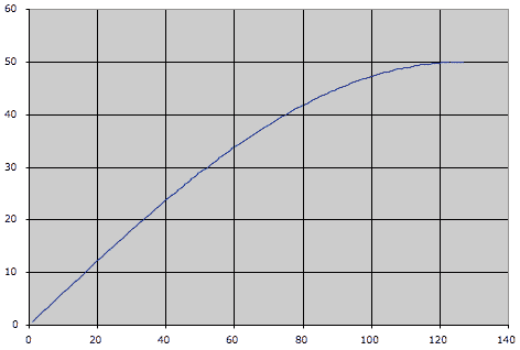
When you open the spreadsheet you’re seeing the 1/4 cycle output in the chart:

the 1/4 cycle Sine wave output

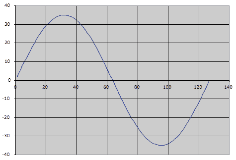
Copy the E5 to I5 range and paste into the E22 to I22 range and you’ll see the result in the chart:

a nearly perfect cycle of a sine wave

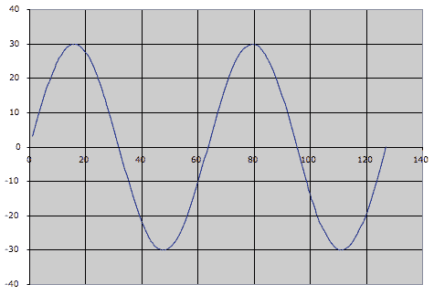
It’s a nearly perfect cycle of a sine wave. To chart out two full cycles, copy and paste E9 to I9:

Charting out 2 cycles of a Sine wave

One thing to keep in mind here is that the CV output limits change as you raise the Drive value. At a 1/4 sine wave setting (Drive value at 0 and a scale value of 34 with Rotary 2 at 0), the Shaper will output a CV value of +50 (it’s not entering the negative range of the bipolar output). At the 4 sine wave settings (Drive value at 91 and a scale value of 2 with Rotary 2 at 4) the Shaper will output a CV vale of +/- 29. The spreadsheet changes all of this for you, and adjusts the chart accordingly.

Viewing the CV value in Thor

  1. To view the CV value in Thor, let’s first make sure we’re seeing true +/-127 values from the Mod Wheel, so place this Thor inside a Combinator, and in Thor’s Modulation Bus Routing Section, make the following assignment:

    Source -> Amount -> Destination -> Amount -> Scale

    Mod Wheel -> 100 -> CV Out 1

  2. Now route CV 1 output on the back of Thor to the Combinator’s Rotary 1 input. In the Combinator’s Modulation Routing Section, make the following assignments:

    Source -> Target -> Min -> Max

    Rotary 1 -> Mod 12 Destination Amount -> -100 -> +100

    Rotary 1 -> Mod 13 Destination Amount -> -27 -> +27

  3. Change Combinator knob 1 from 63 to 64. This visualization isn’t perfect, but it’s fairly close. Raise the mod wheel and note the two amount values in Thor’s Modulation Bus Routing Section rising with the mod wheel. At full throw, they should add up to 127, and at 0 it’s approximately 0 (you may see negative values). Now modify the previous assignment to this:

    Source -> Amount -> Destination -> Amount -> Scale

    Shaper -> 100 -> CV Out 1

  4. Raise the Mod Wheel and you’ll find the values range from approximately +34 down to -36. This is basically a range of 70, so we can essentially call this +/- 35.

So… what is all this good for? What are the applications? I don’t know yet, but it does potentially open up a lot of possibilities for those folks out there with creative and curious minds. One design is a 4 source cross-fader, which is included in the Project files (download above). The Combinator is within a Reason file for maximum compatibility with everyone out there.

Inside this Combinator you’ll notice that the Shaper Driver values for “CV2” and “CV3” Thor units are set for 42, which to my ears extended the fade out time for the mixer faders to a better sounding value. The “CV2” and “CV3” Thor units are identical, except via the Combinator Modulation Routing section, CV3 Thor’s Mod Wheel values are inverted, so the full throw is 0, and the lowest position is 127. This is essentially allowing you to send that sine wave backwards (not upside down) via the Combinator knob. I know, that’s confusing a bit, but sit and stare at your screen for a few hours and it might make sense – it took a while to figure it out, and now it makes sense to me, but it wasn’t easy at first. These Thor units send bipolar CV data to raise and lower the mixer volume levels. When the values go into the negative, those CV values are of no use to the mixer, thus the channels remain at 0 volume. The other Thor, “CV1 and CV4” is sending out linear CV values as opposed to sine wave shaped values – these are being offset via a DC offset value from the two Step Sequencer CV values, one for each CV output. To add a bit of crossfade between 1&2 and between 3&4, adjust Rotary 1 on the “CV1 and CV4” Thor.

Well, that’s about it – hope this is mind-bending for you all.


Ed “EditEd4TV” Bauman

• NOW AVAILABLE ‘Reasonable Help 2010: http://baumanproductions.com/reasonablehelp.html
• Facebook: http://www.facebook.com/pages/EditEd4TV/46599212364
• Reason Files: http://www.baumanproductions.com/reason.html
• Tunes: http://www.soundclick.com/EditEd4TV

High Strung Organ

I was playing around with a bunch of different Thor parameters and came up with a sound I really liked. So I worked on it some more and it turned into this little puppy. It’s not really a true organ, but it sounds somewhat similar. A bright twangy atonal organ.

Download the Combinator: high-strung-organ

Description: I was playing around with a bunch of different Thor parameters and came up with a sound I really liked. So I worked on it some more and it turned into this little puppy. It’s not really a true organ, but it sounds somewhat similar. A bright twangy atonal organ.

Features: The Combinator is fairly simple. It uses a Multi-Oscillator and an Analog Oscillator in Thor. Then it routes the Left part of the audio through a delay, and the Right part of the audio through a Phaser. After that, the two Mixers are used to Cross-fade the signals. You can then use Rotary 4 to decide where the signals are placed: Left or Right. Here’s the complete rundown of the Combinator controls:

Pitch Bend: The pitch bend adjusts the Pitch up or down by 7 semitones.

Mod Wheel: The mod wheel affects the Filter Frequency of the first Filter in Thor. Shifting the Mod Wheel up increases the Frequency a bit.

Rotary 1: Delay Dry/Wet – This controls the DDL1 Delay device’s dry/wet amount from fully dry (turned to the left) to fully wet (turned to the right).

Rotary 2: Shape – Controls the Bipulse Shaper drive from Thor. Increasing this rotary adds more shaper distortion to the signal. Lowering this Rotary lessens the distortion and provides a clearer sound.

Rotary 3: Envelope – Controls the envelope of the High-Pass Filter in Filter slot 1 in Thor. Use this to adjust the tone of the sound being filtered. You can get some very interesting results playing with this Rotary.

Rotary 4: Side Switcher – This crossfades the sounds. Since the Delay and Phaser are placed on opposite sides in the stereo field, this knob allows you to adjust which side you want to place them. When this Rotary is centered, both FX devices are placed center in the stereo field. In other words, there won’t be any panning when the Rotary is dead center.

Button 1: 1st Delay – This turns on the Thor Delay for some synched delay doubling. This simple switch will turn it on (when lit) and off (when unlit).

Button 2: Formant – If you want to completely change the way this patch sounds, you might want to try out this button. In essence, it adds a second Formant Filter in Thor’s second filter slot, so that both Oscillators are routed in series through both the High Pass Filter and the Formant Filter, and then out to the Amp. But this button will give your sound a whole new perspective.

Button 3: Alt Wave – This changes the Multi Osc Wave type for the first Thor Oscillator. When left off, the sound is more bright and distorted due to the saw wave. When turned on, the sound becomes much more dulled. You’ll have to play around with this button and see how it sounds along with changing the other parameters. It can add a whole new element to your sound.

Button 4: Chorus – I didn’t really know what to do with this button. But then I thought about creatinve some really wacky Chorusing, since this sound is already on the wacky side. So I adjusted the Chorus to affect the sound in a pretty severe way. Try it out. When lit, the Chorus is turned on, and when unlit, the Chorus is removed from the signal path.

Usage: You can use this any way you like. But mainly it provides a Synth Lead sound.

Other Notes: You can really change this sound around quite a bit just by playing with the Combinator Rotaries and Buttons. So you’ll have to experiment to find something that suits your taste. I’m sure there are also settings that might not necessarily sit well together because it’s sound range is pretty vast and varied. But I’ve found some pretty useful sounds out of this setup. I hope you do as well. Also note that there’s no finishing touches on it, such as compression or reverb, so this will sound pretty raw as is. You may want to add your own final touches through a second Dynamics Processor Combinator.

As always, please let me know what you think or let me know if and how you use this in your own projects. Happy Reasoning!

10 – Creative ReDrums (Part 2)

In part 1 of our Redrum tutorials, I showed you a few ways you can improve the drum kits in your arsenal by using Thor’s filters, and some M Class Mastering devices. In this tutorial, I’m going to work in reverse and show you how to use the Redrum as a gate CV device to trigger a series of 10 Thors, which act as the drum sounds.

Creative Redrums (Part 2)

In part 1 of our Redrum tutorials, I showed you a few ways you can improve the drum kits in your arsenal by using Thor’s filters, and some M Class Mastering devices. In this tutorial, I’m going to work in reverse and show you how to use the Redrum as a gate CV device to trigger a series of 10 Thors, which act as the drum sounds. This is where things can get pretty interesting, as you can gain complete control over the drum sounds by creating them from scratch using Thor’s Oscillators and Filters. Then, we’ll try to use a technique laid out by Matt Piper in which all the drums are filtered through a Vocoder. This is yet another way to get some beef and boom out of the drums. So let’s work some creative Redrum magic.

The project file contains an .rns file with a single Combinator which outlines a complete drum kit with vocoder filtering, Mastering, and a few extra effects thrown in. Download the Project Files here: creative-redrums-2.

The Basic Setup

  1. Create a Combinator, and inside create a 14:2 Mixer. Then holding Shift down, create in order a Redrum, Spider CV Merger/Splitter, and Thor Synth.
  2. Right-click over the Redrum Pattern section and select “Randomize Pattern” just to quickly add a pattern. For this tutorial, the Redrum is used as a sequencer, and nothing more. You’ll be able to change the Resolution of the Pattern, number of steps, and use the Mute/Solo functions, but samples are not necessary.
  3. Next, Create a Bass Drum sound in Thor. Here’s an example of one way you could go about doing this (see the screenshot below). In the Sequencer section, change the Run Mode to 1-shot, and reduce the steps down to 2. Then in the Modulation Bus Routing Section (MBRS), enter the following:

    CV In1: 100 > Filt1 In

    The Front Panel of Thor with our Analog Bass Drum Sound
    The Front Panel of Thor with our Analog Bass Drum Sound
  4. Now let’s flip the rack around to the back and make our routing connections. First, connect the Left and Right Audio Outputs (1 and 2) from Thor into the Left and Right Audio Inputs on Channel 1 on the Mixer. Then connect the Gate Out on Channel 1 of the Redrum into the Split A input. Send one split output to the CV 1 In on Thor, and send another split to the Gate in (Trig) CV input on the Thor Step Sequencer (at the bottom of Thor).

    Routings on the Back of the rack
    Routings on the Back of the rack
  5. Press Play, and if you will hear the Bass Drum playing. If you don’t hear anything, be sure to check the Pattern in the Redrum and make sure there are some Bass Drum parts in the Pattern Sequencer.
  6. Still on the back of the rack, select the Spider Merger/Splitter and Thor together by shift+clicking on both devices. Right-click and select “Duplicate Devices and Tracks.” Then connect the Left and Right Audio Outputs (1 and 2) from the second Thor into the Left and Right Audio Inputs on Channel 2 on the Mixer. And connect the Gate Out CV from the Redrum second channel into Split A on the Spider CV Merger/Splitter.
  7. Flip the rack around to the front and create a new drum sound in Thor, maybe another Bass Drum or Snare. Repeat this process until you have all 10 Redrum channels filled up. Congratulations! You’ve just created a complete drum kit.

Vocoder Filtering

This trick was shown in Matt Piper’s great Youtube video where he set up a Vocoder to filter his drums. To see the video, visit his tutorial here: propellerhead-record-reason-vocoding-with-drums

  1. Once you have your drum kit set up, go to the back of the rack, and select the Mixer. Hold Shift down, and create a BV512 Vocoder, Thor, and a Spider Audio Merger/Splitter.
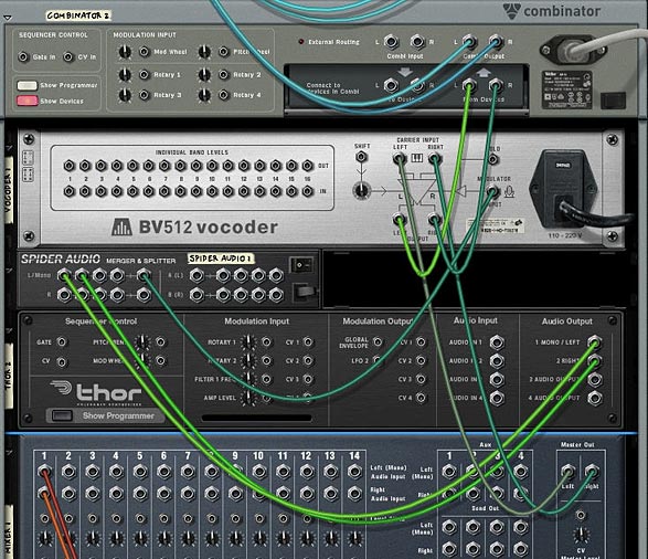
  2. Move the Left and Right Audio input cables on the Combinator (From Devices) to the Left and Right Carrier Input on the Vocoder. Then connect the Left and Right Carrier Output from the Vocoder to the Left and Right Audio input on the Combinator (From Devices).
  3. Route The 1 Mono/Left and 2 Right Outputs from the Thor device to two Left Merge channels on the Spider Audio Merger/Splitter. Connect the Merged output from those two cables to the Modulator Input on the Vocoder. With our routing set up, flip around to the front of the rack.

    Vocoder Routing setup
    Vocoder Routing setup
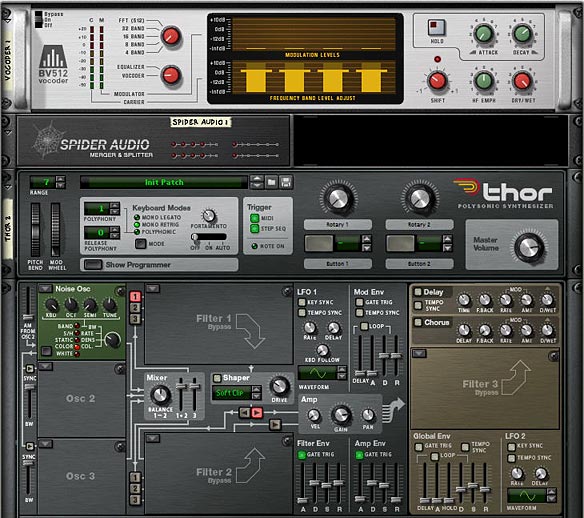
  4. On the front panel of the Vocoder, set the Band Count to 4 Bands (I also found the 8 and 16 bands work well, depending what kind of sound you are looking for). Move the Shift knob to around -24, and Decay to around 80.
  5. In Thor’s global top panel, set the Polyphony to 1, Release Polyphony to 0, and Key Mode to mono Retrig. In the Voice section, add a Noise Oscillator in Slot 1, set the Noise Wave to Color, and Noise Mod to around 36. Then turn on “1” to send the Oscillator to Filter 1 slot (which is on Bypass by the way). Turn off everything else except the Filter and Amp Envelope. In the Step Sequencer section, set the Run Mode to Repeat.

    The front panel settings for the Vocoder and Thor Modulator
    The front panel settings for the Vocoder and Thor Modulator

That’s really all there is to it. Not too complex, just time consuming to create all your drum sounds in the various Thor devices. But it’s very rewarding when you have your own custom drum kit set up just the way you want.

Where do you go from here?

  • You can try the same setup with a stack of Subtractors or Malstrom devices, or any combination of Subs, Mals and Thors to create your custom drum kits.
  • You can add a reverb and a delay to your drums. Also, for an instant doubling effect, you can modulate a button on the combinator to switch from 1-2 steps in all the Thors at once. This doubles up the drum beats (see below for this setup in my own Electro Drum kit).
  • Try going into the Thor which is used as the Vocoder’s Modulator, and switch the Oscillator 1 Noise wave from Color to Static, and then set the Noise mod dial to around 30 or so. You’ll create some very interesting glitch effects.
  • As you can see I’ve added a few effects here and there. There’s two phasers tied to the Hi Hats, for example. In this same way, you can chain some effects into the drums individually. Try adding some scream or even vocoding the drums separately. However, if you do, you’ll have to realize that the more effects, the more CPU intensive this gets. As it is, I only saw 2 bars on my CPU meter. Not too bad. Definitely less intensive than the last kit I put together.

Electro Drums Combinator Controls

Pitch Bend: Unassigned.

Mod Wheel: This controls the Band Count on the Vocoder from 4 bands (no modulation) to FFT (512) when pushed all the way up.

Rotary 1: Voc Filter – This controls the Noise Mod from the Vocoder’s Modulation Oscillator. This can be used to shape the sound of the Drum Filtering through the Vocoder.

Rotary 2: Shift – This controls the Shift parameter on the Vocoder. Again, this can be used to sculpt the sound of the Drum’s Vocoder Filter.

Rotary 3: Pattern Seq. – This knob is used to switch between all 31 patterns in the Redrum. You can assign any patterns you like in the redrum and it will be tied to this knob. In this way, when you’re playing the drums, you can switch on the fly. In my drum kit, I threw in a bunch of random patterns so that you can hear something playing no matter where the knob is set. Note that if the knob is turned fully left, an empty pattern plays (essentially turning the Pattern Sequencer off and silencing all the drums). This is good if you need an empty spot in your song.

Rotary 4: Master Level – This controls the master level of the Submixer, so that you can adjust the drum level globally.

Button 1: Doubler – This doubles all the drum beats via the Thor Step Sequencers. When on, the steps are set to 2, which will play two beats anytime the drum is triggered. When off, only one drum beat will occur when the drum is triggered.

Button 2: Alt Filter – This quickly switches the filters used to modulate the Vocoder, as well as adding a Scream and Reverb effect to the drums. I wanted to make this drum template as versatile as I could, so I thought why not add a completely different sound in the Combinator for some fun. It gives the drum sounds a completely different and more electronic (less organic) sound.

Button 3: Master Bypass – This button controls the Mastering (M Class) devices, as well as the Vocoder filter. If you don’t want to add any mastering or Vocoder Filter to the drums, turn this button on. The Drum sounds are then completely dry (or as they originally sound via the Thors). Leave it off if you want the drums compressed, EQ’d and Vocoded.

Button 4: HH FX – I added some Phaser FX to the High Hats just to give them a different feel. You’ll just have to try it out and see if you like it. I thought it was a cool sound, so I kept it in there as an option for you.

So let me know what you think of this setup, and if you have any other ideas or have some great tips for drum creativity, please feel free to share your comments.

Good Luck!

Ed’s Reasonable Help 2010

EditEd4TV’s Reasonable Help for 2010
Available now at: http://www.baumanproductions.com/reasonablehelp.html


It’s rare that I advocate a specific refill. I can actually count on my fingers how many refills I rely on in my own work, and would rather try and figure out the answer myself or else try building my own instruments and combinators. But when it comes to inspiration and I’m looking to expand my knowledge I can’t think of anyone better than Ed Bauman. In his latest refill offering “Reasonable Help 2010” he provides you with 50 amazing combinators which push the envelope on what Reason can do. And he sets off to prove that most anything you can think of in your head can be worked out in Reason routings and device Combinations.

Without a doubt this is one of the best refills I’ve seen, and it’s not because it’s packed to the brim with a ton of new sounds or new patches. If you’re looking for new sounds, there are other refills out there that can give you off-the-shelf sounds. This refill is aimed straight at the Sound designer who wants to learn how to route devices in reason. It’s also aimed at solving common problems that people face in Reason. How to create a noise gate? How do yo scrub your audio, how do you make reason strum a guitar? All of these questions and more are answered. Other common questions from the forum are answered too. How do you put your vocals through a vocoder to get that Telephone voice? Want an instant Steam Locomotive with Whistle and train speed included. It’s all in there.

In a nutshell, if you’re willing to sit down and look through the patches to see how they are routed, and read the accompanying documentation, you’re going to learn some new tricks and better your Reason skills. If you’re just starting out, you may not entirely be ready for this one. But if you have a decent grasp of how to route your devices together and want to take yourself to the next level, these 50 patches will open your eyes to some brand new ideas. The true benefit of Reasonable Help 2010 is in the educational value. What better way to expand your Reason knowledge than having a 50-session class provided by one of Reason’s top gurus: Ed. He’ll hold your hand the entire way, and speaking from personal experience, he’s always there to help if you get stuck. I highly recommend you purchase your copy now. At $50.00 it’s an awesome deal.

Ed was gracious enough to provide a free .rns file from Reasonable Help: EditEd4TV_GateModifier.

EditEd4TV's Reasonable Help Gate Modifier Combinator
EditEd4TV’s Gate Modifier Combinator

Ed also had some comments about this file, as well as some great insights into his work flow:

The reason I made this Gate Modifier patch was simple – the Slice Output of Dr. Rex is basically useless for triggering synth pads.  I wanted something that could easily serve as an “in-between” module to transform CV data into something more useful.  The concept is pretty simple: just take incoming slice data, which is basically just a small millisecond CV burst, and send that to Thor’s Step Sequencer CV Input Gate In Trigger.  That small gate burst is perfectly fine for triggering the Step Sequencer.  That trigger is used to trigger Thor’s Amp Envelope, which is held open depending upon the value of Combinator knob 1, which adjusts the Step Sequencer Gate Length value.  The Amp Envelope attack and release values are adjustable as well.  There’s also Gate Strength, which can be inverted so it sends negative CV values instead of positive values, which can be used as sort of a “ducking” feature.

So how do I go about this sort of thing?  Well, most of my patches always begin with a need, a want, a solution to a problem.  I always start with a Combinator with a Mixer inside.  I may ditch the Mixer later if it isn’t needed, but that’s the default.  At the heart of most of my problem solving solutions is Thor, since it offers so many incredible ways to take incoming audio or CV and manipulate it to death.  There’s almost always a way to solve a problem with Thor.
 
So sometimes I’ll just decide I’m going to tackle a problem, I’ll make the Combi and put the Mixer in there, along with one Thor, and I’ll just sit there and think, maybe for a few seconds, or maybe an hour or two… just thinking.  I’ll experiment along the way, maybe draw things out on paper so it makes sense visually instead of just mentally (sometimes if I’m away from home and I’m sitting somewhere on a video shoot I’ll start drawing out design concepts that just come to me, I’ll draw them out on paper, you can see 3 of them on the last few pages of the RH’10 PDF manual).
 
The worst is when inspiration hits when I’m driving, and all I can do is dictate the concept into my cell phone, which is somewhat difficult depending on the complexity of the design stuck in my head.  So, once I’ve come up with a solution, and I design it in a Combinator, I’ll sit and stare and think for maybe an hour or so, thinking… “If I’m the end user of this, what will I hate about it, what will I want, what would I change”, and I go about solving those problems.  Sometimes this can be really frustrating because I’ll come up with additions before I stumble upon some solutions, so I may end up programming knobs 3 and 4 to do something, then I discover it’s a much better solution if I have, say, the Mod Wheel do the same job as those two knobs, so I have to redesign my modulation routings and perhaps some CV cabling as well.
 
Eventually I land on the final design, and I’ll have some buttons or knobs left over empty, so I’ll try to come up with some fun stuff at that point.  That’s when I wish the Combi Pitch and Mod Wheels had labels as well, since they’re stuck being labeled via the Combi skin… Sometimes I use those two wheels for other things and I’m too busy/lazy to design a custom skin for those different purposes.  Also, I try to avoid tying up a knob with the “do not touch!” label, though sometimes it’s necessary.  And that’s when I wish the Combinator was 8×8 instead of 4×4, and I wish it had, say, 8 CV inputs and 8 CV outputs on the back as well, not necessarily tied to the knobs if you don’t want them to be.

And here is an explanation of the inner workings of the rns file, direct from Ed’s PDF documentation:

EditEd4TV_GateModifier

This Combinator allows you to modify/extend Dr. Rex gates into a more useful state.

Knob 1 “Gate Length”: This knob adjusts the gate length.

Knob 2 ” Gate Strength”: This knob adjusts the gate strength.

Knob 3 ” Gate Attack”: This knob adjusts the gate attack time.

Knob 4 ” Gate Release”: This knob adjusts the gate release time.

Button 1 “2 Ordered”: This button switches the gate mode from single to two varying triggers.

Button 2 “16 Random”: This button switches the gate mode from single to 16 random triggers.

Button 3 “n/a”: This parameter is unassigned.

Button 4 “n/a”: This parameter is unassigned.

Pitch Wheel: This wheel is unassigned.

Mod Wheel: This wheel is unassigned.

Details: This Combinator is particularly useful when used with a Dr. Rex loop player. On the rear panel of Dr. Rex you’ll find a Slice Gate Output. Note that this CV signal is routed to the Spider CV Slice Splitter – this is purely for demonstration purposes. Note that the first split output is routed directly to Thor 1 Pad’s Filter 1 Frequency Modulation Input, whereas the second split output is routed through the GateModifier, then into Thor 2 Pad’s Filter 1 Frequency Modulation Input. Play back the demonstration sequencer and solo Mixer channel 1. This is the drumbeat that we’re using to send gate signals to the two Thor units. Return the Mixer back to normal and now solo Mixer channel 2. This is Thor Pad 1. Notice very short and barely useful clicks in the audio signal, which is a result of the very short slice gates affecting Thor’s filter. Return the Mixer back to normal and now solo Mixer channel 3. This is Thor Pad 2. Notice the much more active and useful affects on the audio signal, which is a result of the GateModifier creating better gate signals.

Inside the GateModifier you’ll find a single Thor unit. CV control needs to come directly into this Thor, into the Step Sequencer CV Input Gate In (Trig) jack. Each incoming slice gate will trigger a step in the Step Sequencer. This first step is set for a gate of 0%, but Combinator knob 1 (Thor Rotary 1) is used to adjust this gate length up to 100%, thereby creating much more useful gate lengths. This new gate signal triggers Thor’s Amplitude Envelope, which is then routed to both CV 1 and CV 2 outputs, where CV 2 is a polar opposite of CV 1. Though not used in this demonstration, know that CV 2 output is ready for use if needed as an inverted output. Combinator knob 2 is used to trim the strength of both of these outputs. Note that Combinator knob 2 is bipolar, with no affect on strength when centered. Right of center results in positive results (with negative results from CV 2 output) and left of center results in negative results (with positive results from the CV 2 output).

Combinator button 1 is used to change the number of steps of the Step Sequencer from 1 to 2, in a back and forth pattern. Step 2 contains modified parameters that create a different result than step 1, thereby making a noticeable difference in how the gated signal controls Thor. Combinator button 2 is used to change the number of steps of the Step Sequencer from 1 to 16, in a random pattern, with all 16 steps set for variable settings that result in an unpredictable, yet still slice accurate, gate signal.

Combinator knobs 3 and 4 adjust the Amplitude Envelope attack and release times, respectively.

In our example we’ve sent the gated signal to Thor’s Filter 1 Frequency Modulation Input CV jack, but you can of course route this signal anywhere you like. You’ll find this new signal works much better than the standard slice output of Dr. Rex. This GateModifier is also useful to modify the gate signals coming out of a ReDrum, where the ReDrum channel is set for gate mode 0 (sawtooth wave). Though you can get workable results by switching the ReDrum gate mode to 1 (square wave), this potentially affects the ReDrum channels audio waveform; in the case of, say, a crash cymbal, the affect of switching the gate mode to mode 1 are more often than not unacceptable (muted crashes). The alternative is to sacrifice a ReDrum channel to use purely as a gate signal in mode 1, which may also be unacceptable. Your best option may be to use the GateModifier Combinator, allowing you to select any gate output for use.

The Dr. Rex, Spider CV, Thor units, and sequence in this file are provided simply to test the Combinator’s features.


A huge thanks to Ed for putting this package together. You truly are an inspiration to all of us Reason users. Please keep doing what you’re doing and I look forward to your future products as well. You can purchase Ed’s Reasonable Help 2010 here:  http://www.baumanproductions.com/reasonablehelp.html

9 – Creative ReDrums (Part 1)

I decided to try out some Redrum creativity by taking a standard Redrum patch from the Factory Sound Bank and punching it up. At the same time, I tried to get creative with the Filtering and Routings. A new way to use your Redrum device.

I often get asked and see on the Props forum many complaints that the supplied drum kits are lacking in depth and sound flat. Often this takes the form of slams against the props for providing lacklustre drum kits in the Factory Soundbank. Truth is, the drum sounds can be expanded upon, and if you’re willing to take some time, they can be made to sound much deeper and more punchy. It’s all in what you do with them. The power is all there in front of you, and with the Redrum there’s a lot of flexibility.  

With this in mind, I decided to try out some Redrum creativity and put together a flexible drum kit that takes a basic kit from the props and turns it into something unique . There’s two things I want to accomplish with this tutorial: First: Create a Drum Kit that is more expansive sounding, and Second: Find some creative ways in which the Redrum can be used. So let’s see how far we can take it.  

Before jumping in let me first say that this template is fairly massive. It contains a lot of Thor filters, and as such it can be a little expensive on CPU. If you find it taxing your CPU, you can scale it down (see my notes in the “Where do you go from here” section below), or you can bounce it to an audio track to be put into a Dr. Rex device or as a separate audio track entirely. Second, there’s two main ways I find can bolster the sound of your drums: Compression/Mastering, and Filtering the drums, so those methods will be explored below.  

Download the Project files here: creative-redrums. The project files contain two Combinators inside an rns file. The first Combinator is the Original untouched kit put through the same Matrix sequencing. The second Combinator is the Drums we’re going to create below. Mute/unmute the channels in the mixer to listen to how they sound compared to one another.  

  1. As with all great Reason patches, let’s start by creating a Combinator. Inside the Combinator, create in order, an M Class Compressor, M Class Equilizer, M Class Stereo Imager, M Class Maximizer, 14:2 Mixer, Redrum Drum Machine, Thor Synth, DDL-1, and Spider Audio Merger/Splitter. Then hold Shift down and create a Matrix Pattern Sequencer.
  2. Flip the Rack around and let’s start working on our Routings. First, move the Cables from the Combinator’s “From Devices” ins to the Audio Inputs of the Compressor. Then connect the Audio Outputs from the Maximizer to the “From Devices” inputs on the Combinator. This sets up the main mastering for the Redrum.

    The Mastering setup on the back of the rack
    The Mastering setup on the back of the rack
  3. Next, move the DDL 1 Left and Right input cables to the Left and Right Channel 1 on the 14:2 Mixer. At the same time, disconnect the Chaining Aux cables from the 14:2 Mixer. Also, connect the Left output from Channel 1 on the Redrum to the Audio In 1 on the Thor. Then connect the Right output from Channel 1 on the Redrum to the Left input on the DDL-1.
  4. Next, move the Left and Right Audio Inputs from Channel 2 on the Mixer to two Left Audio Inputs on the Merger side of the Spider. Then route a cable from the Left Merged Output to Audio In 2 on Thor. With this setup, you’ll have no delay on the Left audio channel for the drum, while the Right Channel goes through the delay device.
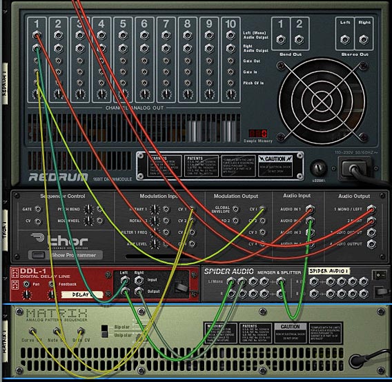
  5. Moving to our CV routing, plumb a CV cable from the Gate CV output of the Matrix to the Gate In on Channel 1 on the Redrum. And plumb a CV cable from the CV 1 Output on the Thor to the Pitch CV In on Channel 1 of the Redrum. Also cable the Note CV output from the Matrix to the CV 1 Input on the Thor, and the Curve CV output from the Matrix to the CV 2 Input on Thor. If this is all starting to get confusing for you, check out the routings in the Combinator file download, or else check out the image below.

    The routings for the Thor Filter, Delay, and Matrix Sequencer
    The routings for the Thor Filter, Delay, and Matrix Sequencer.
  6. Next, let’s flip the rack around and start working on applying settings to the front of the devices. First, click the “Enable Pattern Section” button on the Redrum so that the pattern is disabled. Click the browse button and load a patch (drum kit) into Redrum. I used the Chemical Kit 7 from the Factory Soundbank (under Redrum Drum Kits > Chemical Kits). Now you have a basis from which to work.
  7. In Thor, we’re going to use multiple filters which will be applied to the Bass Drum (Channel 1 on the Redrum). So the first thing to do is to ensure that the Bass Drum Left and Right channels are routed into Filter 1 and Filter 2. In the Mod Matrix, apply the following settings:

    Audio In1: 100 > Filt1 In  

    Audio In2: 100 > Filt2 In  

    This setup means that the Left (dry) Channel goes through Filter 1, while the Right (delay) Channel goes through Filter 2, and then both are sent in Stereo to be output to the Submixer. 

  8. Next, since Thor is not free running, like the Subtractor, we need to use the step sequencer to keep Thor “On.” To do this, set up a one step long pattern in the sequencer. Turn Button 1 on (so it’s Red) on the top panel of Thor. Then add the following setting into the Mod Matrix:

    Button1: 100 > S. Trig  

    To be honest, since everything will be triggered when you hit the play button, you probably don’t need to setup the above (step 8). But it will ensure that Thor remains on and is running, which will ensure you can use the filters in the Voice section of Thor (the first two filter slots), as well as the Global filter section (Third Filter slot).  If I’m wrong, please feel free to correct me.

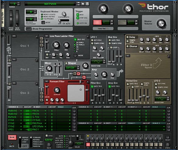
  9. Add a Low Pass Filter into Filter slot 1, and a Formant Filter into Filter slot 2. Route both the filters parallel into the Amp section of Thor. Turn off any Oscillators and Oscillator routings, as well as the Mod Envelope and Global Envelope sections. And Then add the rest of the MBRS settings as follows:

    CV In1: 100 > CV Out1 (sends the Note CV data from the Matrix to the CV Pitch in on the Redrum Channel — yes you can send the CV cable directly from the Matrix to the Pitch In on the Redrum, but If you set it up this way, you can then use the Note CV to affect other parameters in Thor, if you wish).  

    CV In2: -75 > Filt1 Freq (sends the Curve CV data from the Matrix to the Filter 1 Frequency).  

    CV In2: 75 > LFO 1 Rate (sends the Curve CV data from the Matrix to the LFO 1 Rate).  

    LFO1: -46 > Filt2 Y (sends the LFO 1 to the Filter 2 – Formant Filter – Y Parameter).  

    Here’s the image which shows the front of the Thor Device and the Filter settings:  

    Thor settings for the main Bass Drum Filtering
    Thor settings for the main Bass Drum Filtering
  10. Next, on the DDL-1, select 4 Steps, and in the Matrix, create a Random pattern. Alternately, you can build your pattern as you play the sequence. The Matrix will trigger the Drum’s Channel 1 gate, and play the pattern you enter. So it can be much easier to build up a drum pattern as you play. Also, as you play, adjust the filter settings in Thor until you come up with your own unique brand of Drums. At the same time, flip the rack and adjust the Pitch In Trim knob on the Redrum Channel 1 to taste.
  11. Now comes the tedious part. Select the Thor, DDL-1, Spider Audio Merger/Splitter, and Matrix. Then right-click and select “Duplicate Devices and Tracks.” Once duplicated, flip the rack around to the back of the devices, and set up the routings into the second Channel of the Redrum and Submix (along with the CV routings, etc.). Do this for each Channel of the Redrum.
  12. Once everything is routed properly, you can start to work on filtering each individual drum channel. Try out different Thor filters, as well as different Matrix patterns (right-clicking and using “Alternate Pattern” works well here, along with shifting the patterns left or right). Also try alternating some of the delay routings from left and right (by reversing the audio inputs on the back of the Thor. Finally, try out different delay steps for each of the delays. There’s lots you can do to fine tune this type of setup.

Combinator Mod Matrix

Going into all the modulations in the Combinator is pretty intense, so instead I’ll let you download the project files and see what’s going on. But a few words about how the Rotaries/Buttons work:  

The Pitch Bend moves all the drum pitches up or down. This can be fun to play with while performing with the drums. The downside is that when the Pitch Bend is static center, so are all the drum pitches. But you can always automate it so that it stays in a non-static, non-centered position.  

The Mod Wheel is tied to a basic drum Reverb which also affects all the drums equally. If you don’t like this Reverb, you can use your own. This way you can apply a little or a lot of Reverb to the overall mix. And then of course there’s nothing saying you can’t add a Reverb or other FX as Send FX on the Submixer. This was a last-minute thought.  

Rotary 1-3: Applies Compression, EQ, and Maximizer Gain to the overall mix. In this way you can master the drums to your liking.  

Rotary 4: Affects the Delay Levels for all drums at once. You can go from no delay (at the far left) to a pretty heavy delay (on the far right).  

Buttons 1-3: Turns on/off the delays for the Bass Drums (1), Snare Drums (2), and High Hats (3).  

Button 4: Turns on/off the Ride by muting it on Channel 10 of the Submixer.  

Where do you go from here?

  • Add different variations and drum patterns (fills and rolls) in the Matrix pattern sections. Then create sequencer tracks for all the Matrixes. In this way you can play the patterns for each of the drums in their own separate tracks on the sequencer, and they are all pattern-based. This makes creating several variations very easy not only to explore, but also to apply in your song.
  • If things are a little too chaotic having all 10 drums running at once, simply mute some of them in the Drum Submixer, so let’s say you have a Bass Drum, Snare, and Hi Hat instead of an all-on cacophony of drums.
  • At the same time, if the CPU load is a little too much, try minimizing the number of filters used, and instead run each drum channel through only one filter, instead of two. Or delete the drums you aren’t using, along with their associated Thor/Delay/Splitter/Matrix.
  • Once you have this template built (and you already have mine done for you), you can add different drum kits into Redrum, and adjust settings for your filters, mastering, etc. One thing that helps is to work on the drums in a build-them-up-as-you-go way. So first do the Bass Drum, then mute the bass drum and go on to the Snare, then unmute and see if they work together. Once they do, move on to the next drum.

And no more than a few days after I posted this article, Matt Piper posted a great little youtube tutorial on how to process your drums through a BV512 Vocoder. You have to check it out. It sounds awesome. Great inspiration for those that want another way to beef up your drum kits: propellerhead-record-reason-vocoding-with-drums

So let me know what you think of this setup. Do you know of some great methods for getting more out of the drum sounds provided in the Factory Soundbank? Do you have any creative drumming techniques. Please feel free to share them. I’d love to see what can be done to boost the supplied drums and learn some new creative ways to ReDrum the kits. Good luck in your Reason projects!

Psychedelic Leaves

The ultimate in Combinator Backdrop design. This one file extends the functionality of the original Reason template and takes it to new levels of flexibility. Select from 5 Rotary scales, 3 front plate designs, and 28 Combinator names. Plus adjust every single design element independantly.

Download the Backdrop File (PSD – Photoshop) here: backdrop-psychedelic-leaves.zip
Requirements: Photoshop 6.0 and above.

Description: The ultimate in Combinator Backdrop design. This one file extends the functionality of the original Reason template and takes it to new levels of flexibility. See the features (outlined below the images):

Psychedelic Leaves Backdrop: showing the "Inner Plate" design and 4 different Rotary Scale styles
The "Outer Plate" style.
The "Glow Plate" design with separated plates.

Features:

All aspects of the design can be customized since everything is on separate layers. The following can be customized for all elements (both text and image elements):

  • Opacity of the Layer
  • Use of Layer Blend Modes on every layer
  • Color
  • Layer Styles
  • Hue/Saturation and other Adjustment Layers

Five types of Rotary Scales can be selected (all scales except the default Hash Scales are shown in the above images):

  1. Hash Scales (Reason’s default)
  2. Point Scales
  3. Bipolar Arrow scales
  4. Ramp Scales
  5. Bipolar Ramp Scales

Three plate designs (shown in the above images):

  1. Outer Plate with Rivets
  2. Inner Plate with Inner drop shadow and adjustable gradient overlay
  3. Separate Glow Plate design

28 Device Names are included and placed in the top-right section of the Combinator, so they are visible even when the Combinator is minimized. Note that you can also adjust the color, opacity, text, layer style, etc. of each name separately (for example, to create separate sets of backdrops for each). The names basically follow the folder structure of the Factory Sound Bank. Select from the following Combi names:

  1. Example Combi
  2. Test Patch
  3. Loop Player
  4. String Section
  5. Voice & Choir
  6. Sound FX
  7. Woodwind
  8. Reed & Pipe
  9. Performance
  10. Pads & Textures
  11. Polyphonic Synth
  12. Synth Lead
  13. Piano & Organ
  14. Orchestral
  15. Percussion
  16. Drums & Beats
  17. Bells & Mallets
  18. Guitar Player
  19. Bass Player
  20. Vocoder
  21. Pattern Seq.
  22. Modulation
  23. Mastering
  24. Fidelity FX
  25. Chorus / Flanger
  26. Reverb Device
  27. Dynamic Processor
  28. Digital Delay

Top and Bottom of the Background is divided into separate layers so you can fill the top and bottom with different designs, fill colors, images, etc. The top portion has transparency locked so you won’t accidentally fill in the bottom portion. So it’s as safe as can be.

A logo layer where you can add your own logo into the design. I might possibly extend this to create an image area for the logo so you can use either an image or text. Right now, the logo is text-based.

The bottom portion of the background has a simple gradient fill layer in which you can adjust how much gradient (lighting) to apply to the design (or turn it off by hiding it if you wish).


Basically, you have a wide degree of control over the look and feel of the basic design. Let me know what you think, and let me know if there is a way I can add to this or make further adjustments. Right now, I’ve made it very flexible. But I’m always looking at ways I can expand on this design and future designs.

Oil Paint & Roses

I wanted to extend the functionality of the Combinator Backdrop Template that comes with the Reason software. And so I developed these two little puppies, which allows you to fully customize the look and feel of the design. More backdrop designs will come, as time permits.

Download the “Oil Paint” Backdrop File (PSD – Photoshop) here: backdrop-oilpaint.zip
Download the “Roses” Backdrop File (PSD – Photoshop) here: backdrop-roses.zip
Requirements: Photoshop 6.0 and above.

Description: I wanted to extend the functionality of the Combinator Backdrop Template that comes with the Reason software. And so I developed these two little puppies, which allows you to fully customize the look and feel of the design using Photoshop 6 and above. More backdrop designs will come, as time permits. Read below the images for the full listing of features:

The Oil Paint Combinator Backdrop
The Roses Combinator Backdrop: adding a little flare to your combis

Features:

  • Three types of Rotary Scales can be selected (more will be added in future Backdrop designs): 1. Hashmarks (Reason’s default); 2. Point (shown in the above image); 3. Bipolar Arrow scale (in case the Rotary is bipolar. Note that you can mix and match between the Rotary scales depending on your setup. For example, if Rotary 1 is bipolar, you can select the “Bipolar Arrow” for Rotary 1 and select “Point scale” for the other 3 rotaries. They are all on their own individual layers within the sets. If you want to use all one scale, elect to show the entire set at once.
  • Top and Bottom of the Background is divided into separate layers so you can fill the top and bottom with different designs, fill colors, images, etc. The top portion has transparency locked so you won’t accidentally fill in the bottom portion. So it’s as safe as can be.
  • All elements are on their own layers, so you can make adjustments to each section of the design (for example, adjusting the opacity of each element individually).
  • Device name is located in the top right section of the Combinator, so that when it is minimized, you can still see what device you are looking at. And more importantly, names of all the different possible devices are on separate layers, so you can select the device name you want.
  • Color Fill Layers and Hue/Saturation Adjustment Layers sit on top of all other layers, so they are fully customizable. Customize the colors of each text layer independently, as well as the background, scales, labels, etc. All of this is fully customizable on an element by element basis.
  • A logo layer where you can add your own logo into the design. I might possibly extend this to create an image area for the logo so you can use either an image or text. Right now, the logo is text-based.
  • The bottom portion of the background has a simple gradient fill layer in which you can adjust how much gradient (lighting) to apply to the design (or turn it off by hiding it if you wish).

Basically, you have a wide degree of control over the look and feel of the basic design. Let me know what you think, and let me know if there is a way I can add to this or make further adjustments. Right now, I’ve made it very flexible. But I’m always looking at ways I can expand on this design and future designs.