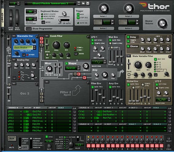
15 – Switch Devices with a Rotary

The Question: How do you switch between multiple devices using a single Combinator Rotary. There are two methods to do this, one being good for those who have Reason 3, and the other more advanced method for those that have Reason 4 or Reason+Record. Learn both of these methods.

The Question: How do you switch between multiple devices using a single Combinator Rotary. There are two methods to do this, one being good for those who have Reason 3, and the other more advanced method for those that have Reason 4 or Reason+Record. The first method I’m going to call the “Matrix” method. The second is brought to us by Ed of EditEd4TV fame, and I’ll call this the “Thor Step Sequencer CV” method.

You can download the project files here: instrument-switchers. These include 2 .rns files outlining both methods below. I’ve also included the proper way to create an “Equal-Power Crossfader,” which seemed appropriate given that we’re talking about how to switch from one instrument to another. So if you have only 2 instruments and want to crossfade between them, you can look at the .rns file in the project file download to see how it’s done. If you want to learn more about it, you should read Peff’s detailed tutorial explaining this process over at the Propellerhead User Forum: One Hand in the Mix — Building Crossfaders using the Combinator. Anytime Peff offers something for you to read or download, you should always take advantage of that. His work is several notches above everyone else. And I’m not kidding!

This crossfader method has always been one of my favorites and one of the most useful building blocks in Reason, simply because you can use it in a variety of interesting ways, and map it to your hardware controller’s crossfader, if it has one.

The “Matrix” Method (for Reason 3 and up)

This method is the less preferred of the two methods, because there is a delay or lag involved in using the Matrix in this way. You can, however, change the time signature to 1/4 to reduce the lag, but any way you slice it, there will be a slight pause when transitioning from one instrument to the other using the Combinator Rotary. This just can’t be fixed. However, it doesn’t mean you can’t find some use from this method, and if you’re using Reason 3.0, then this is really the only solution you have, short of programming your mute/solo buttons in the sequencer. The method works like this:

  1. In the combinator, let’s say you have 8 NN-XT devices, and all the devices are connected to a 14:2 mixer on their own channels. Create 8 matrix devices under the mixer and set them all to “Curve.” The curve should be unipolar. Program each of the matrixes to have the same 1-note, 1-step pattern. The level of the 1-step pattern should be raised fully. Now each subsequent matrix will have the pattern programmed on the next bank that follows, like below:

    Matrix 1: A1; Bank A2-A8 should have the curve set to zero (fully off)
    Matrix 2: A2; Bank A1 and A3-A8 should have the curve set to zero (fully off)
    Matrix 3: A3; Bank A1, A2, and A4-A8 should have the curve set to zero (fully off)
    Matrix 4: A4; Bank A1-A3 and A5-A8 should have the curve set to zero (fully off)
    and so on. . .
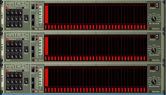
    The Matrix pattern banks
    The Matrix pattern banks: 1-step pattern for each bank. This image shows the first 3 matrixes -- Bank A1, A2, and A3. All other patterns on all other banks are turned completely off
  2. Flip the rack and connect the curve CV from each of the matrixes to the levels in on each of the 14:2 mixer channels for each of the devices. Then turn the trim knob all the way right for all the level CV ins on the mixer.
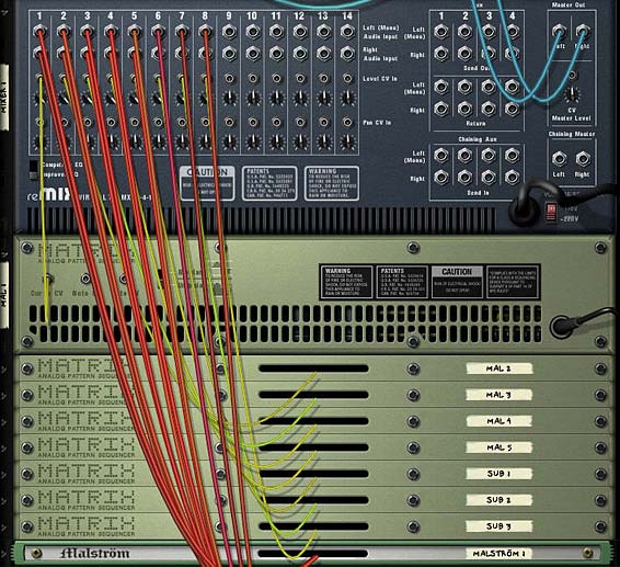
    The Matrix Curve CVs connected to the Level In CVs on the ixer
    The Matrix Curve CVs connected to the Level In CVs on the Mixer
  3. Flip the rack around to the front, and set all the fader levels for all 8 channels on the mixer to zero (fully down).
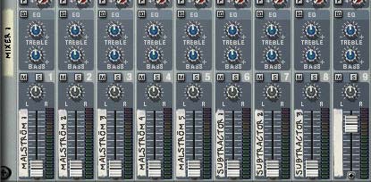
    The 14:2 Mixer with all Level Faders turned down
    The 14:2 Mixer with all Level Faders turned down
  4. Finally, program the same Combi Rotary for each matrix to affect the “Pattern Select” parameter with min: 0 and max: 7.

Now, when you turn the Rotary knob, it will run through all the matrix patterns and essentially only have one device playing at any given time. Each Matrix controls the level of each device, and only opens one device’s level at any one time.

It sounds much more complex than it is. But with this method, you can actually have the rotary adjust up to 32 different device levels; 1 device for each matrix pattern bank. There’s probably even a method to control more than this using 2 combinators linked together, but I haven’t delved that deeply into it, and I doubt you’d ever need to control more than 32 devices with a single Rotary. Perhaps that’s something which could be explored in another tutorial down the road. For right now, I’m much more excited about the next method below, used to control your instruments.

The “Thor Step Sequencer CV” Method (for Reason 4.0 or Reason+Record 1.0 and up — we hope!)

The second method capitalizes on a quirk in Reason which applies only to the Reverse or Random modes of the Thor Step Sequencer. Since this is a quirk, if the Props decide to “fix” this quirk in a future version of Reason or Record, we may be out of luck (and stuck with several Combinators that need to be redesigned), so hopefully this is a quirk that stays with Thor on into the future.

  1. First, let’s build on what we previously did with the “Matrix” method. So open up the Combinator that you just built, and delete all the Matrix devices. Instead, in their place, create a Thor sequencer, and turn everything off. All the green lights need to go off, all the polyphony and pitch bend settings should be set to zero, and all the sliders in all the envelopes need to be turned down. Then bypass all the oscillators and remove all the filters. Just start at ground zero.
  2. Next, in the Modulation Bus Routing Section (MBRS), enter the following settings:

    S.Curve 1: 100 > CV Out1

    S.Curve 2: 100 > CV Out2

    Seq.Note: 100 > CV Out3
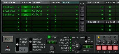
    The MBRS settings and settings for Curve 1
    The MBRS settings and settings for Curve 1
  3. In the Step Sequencer, set the Run Mode to “Step” and the Direction to “Reverse.” Also set the Octave setting to “Full.” Set the Edit knob to “Curve 1,” and set up the Step 1 curve to “100.” Then set curve 1 steps 2-8 to zero.
  4. Move the Edit knob to “Curve 2,” and set up the Step 2 curve to “100.” Then set curve 2 steps 1 and 3-8 to zero.

    The Thor Step Sequencer with the Curve 2 settings
    The Thor Step Sequencer with the Curve 2 settings
  5. Turn the Edit knob to “Note” and set up the Step 3 note to “E6.” Then set the note value for steps 1, 2, and 4-8 to “C-2.” C2 gives off a CV value of zero, while E6 gives off a CV value of 100. In this respect it acts just like the Curve values.

    The Thor Step Sequencer with the third step "Note" setting
    The Thor Step Sequencer with the third step "Note" setting
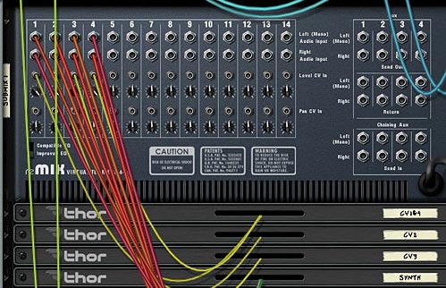
  6. Flip the rack around and pipe the first 3 CV outs from Thor to the first 3 Level CV ins on channels 1-3 on the 14:2 Mixer. Duplicate the Thor two more times. The second Thor will handle steps 4-6 (Mixer channel 4-6 level CVs), and the third Thor will handle steps 7 & 8 (Mixer channel 7 & 8 level CVs).
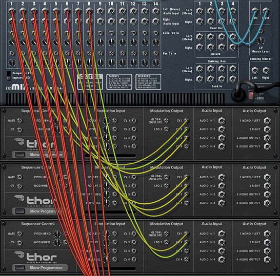
    The Thor CV cabling into the Level CV ins on the Mixer
    The Thor CV cabling into the Level CV ins on the Mixer
  7. Finally, go into the Combinator Mod Matrix and program the following for each of the Thor devices:

    Rotary 1 > Step Count: 1 / 8

The Combinator setting for Rotary 1. All 3 Thors need this same setting
The Combinator setting for Rotary 1. All 3 Thors need this same setting. Note: The above image was taken with Reason 4. This used to be called the "16 S Sequencer Step Count" located at the bottom of that gargantuan list of assignable targets -- where you'd have to scroll to the bottom of the list. In version 5, it's now under "Sequencer > Step Count."

Now, when you turn the Rotary 1 knob, it will run through all 8 devices acting like a mute/solo button for all devices. If you think about the way this is working, it’s exactly like the Matrix idea, except you’re using the Step Sequencer in Thor. Each Thor handles 3 different mixer channels, and you can handle up to 15 devices at once with a Rotary (you can’t use the 16th step in the Step Sequencer in this way — but you can use all other 15 steps to control your instruments).

And here’s the magic numbers for the transitions between the 8 devices, using the Rotary:

Instrument 1: 0-18

Instrument 2: 19-36

Instrument 3: 37-54

Instrument 4: 55-72

Instrument 5: 73-90

Instrument 6: 91-108

Instrument 7: 109-126

Instrument 8: 127

Looking at these numbers, you’ll see that everything matches up just fine except the transition between instrument 7 and 8. Not sure why that is, but it’s a little quirky. Still, this technique is instantaneous between all the switches.

I haven’t yet taken a look to see what else can be done with this technique, but it certainly opens the door to a lot of other possibilities. If I get a chance, I’m going to try exploring some other avenues with this little trick and I’ll keep everyone posted. Let me know what you think of this tutorial, and if this will help you build your own patches. And thanks go out to Ed for taking the time to show me how this worked. If it weren’t for guys like Ed, we’d still be working on our patches in a cave.

Until next time, happy Reasoning and Recording!

14 – Layered Synths with a Theme

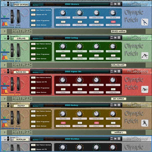
Layered Synth Patches to celebrate the 2010 Olympic Winter Games in Vancouver. A creative way to present some sound themes in Reason and Record.

This is going to be a little different from my past tutorials. Since this is just as much a forum for creativity as it is a forum for ways in which you can get the most out of Reason and Record, I wanted to take a little time out to offer up an idea I had the other day while watching the Olympics.

Download the project files here: olympic-patches. There is one Reason (.rns) file which contains 5 Combinators. The matrixes that are attached to each of the Combinators are there to preview the sounds. You can mute/unmute the Mixer channel to hear the proper Combinator. They are not meant to be played with each other. Though if you can find a creative way to do this, have at it!

I thought to myself, what about creating a themed set of Combinators, which are based solely on layered synths. The idea came as I was watching the speed skating competition and I started getting some ideas for sounds running through my head. So while I had Record opened, I started working on creating what I felt was the sound of skaters. This further led to the thought: Why not create a series of patches based on the sounds of the Olympics. Now, there’s 15 different events in the Olympics, and that means a lot of Combinators and a lot of programming. So before I go completely nuts with this idea, I decided to first offer up 5 patches for 5 different events.

Here’s a few sound samples using the “Speed Skaters,” “Curling,” and “Alpine Ski” patches:

And here are a few more sound samples showcasing the “Hockey,” and “Biathlon” patches:


Olympic Patches: 5 Layered Synth Combinator Patches
Olympic Patches - A tribute to the 2010 Vancouver Winter Olympic Games

The main premise was to create Combinator patches that encourage you to explore the rotaries and buttons without any preconceived notion of how they are planned out or mapped to the devices inside. So for that reason, I’m not going to go into detail on how things are routed. Rather, I’d prefer if you gave them all a listen and use your ears to explore the types of sounds these patches can generate. So try them out, and give them a whirl. Let your ears be your guide as you make adjustments. And once you’ve done that, then feel free to take a look and see how they are programmed.

I have to say I felt a little sense of pride putting these together, since I’m originally from Canada, and Canada was putting on this year’s Olympic games. The feather in the cap however, was when Canada won the Gold Medal in the last Olympic event yesterday: Men’s Hockey. I have to say, that made my night.

Do you have any Layered Synth ideas of your own that you would like to share here? Do you like these patches? Anything you would do differently. Please feel free to start up a discussion about them. Do they inspire you to create your own themes? What kind of theme would you create? What do you turn to for inspiration? I’m curious.

13 – Glitch Boxes

In this project, I’m going to create a few Glitch Boxes, and show you some techniques to get a little more glitch out of Reason. Though Reason isn’t built to be a glitch plugin, there are several ways you can connect things up to get some glitch mayhem from the devices.

In this project, I’m going to create a few Glitch Boxes, and show you some techniques to get a little more glitch out of Reason. Though Reason isn’t built to be a glitch plugin, there are several ways you can connect things up to get some glitch mayhem from the devices. When you then combine them all, you can have yourself a field day playing around with the knobs, wheels and buttons and work them into your own compositions.

So here I’m going to provide 3 different Glitch Boxes (incidentally they are color-coded just for fun), and go over some of the techniques that I think make them unique. Before I start, let me point out that I’m not going to go through the process of creating the Combinators from start to finish. Rather, I’m going to use the technique I outlined in the “Creative Redrum” tutorial series, where I added 10 synths and used gate triggering from the redrum to play these synths. The synths are the main glitch sounds, and these can be anything you like. The point is how you can use those sounds inside the combinator, and how you can add stylistic effects to get more out of them.

So let’s start our glitch journey in Reason.

The file for this tutorial can be found here: Glitch Boxes. The zip file contains 3 Combinators inside an .RNS file, each of which is attached to a mixer. To hear one of the combinators, just mute the other ones on the mixer. They weren’t designed to be played together, however, this was the easiest way to provide them to you all at once. Feel free to save them as Combinator patches and/or use them as templates where you can add in your own sounds into each of the 10 different synths in each of the Combinators. Also, don’t forget that you’re not only getting access to 3 patches, but you’re getting access to 30 synth glitch sounds as well. Enjoy!

Glitch Box 1 (Blue – Thors)

This Glitch Box uses 10 Thors to generate 10 different Glitch sounds, which are triggered by the Redrum Sequencer. The Redrum in turn has 32 patterns which are 64 steps each for a maximum Glitch mayhem. The interesting part of this patch is the way the Auto-sequencer is setup. By pressing the fourth button on the Combinator, the Auto-Sequencer kicks in and takes control to provide a very random output. It’s very easy to set this up. You just need to create a few Matrixes, and then send the Curve (or Note or Gate) CV into the Combinator CV inputs to control the overall playback of the Combi, or else any one of the Rotaries or Pitch/Mod wheels.


The rest of the Combinator patch is similar to the Creative Redrums 2 and Creative Redrums 3 tutorials, so I’m not going to delve into that right now. Please feel free to read through those tutorial in order to get familiar with the methods used to put together these patches. 

Here is a rundown of how this Combinator’s Rotaries and Buttons work:

Pitch Wheel: This raises or lowers the pitch of the 10 Glitch sounds at once by +/- 7 semitones.

Mod Wheel:  This dampens the sound of the Higher pitched Glitch sounds, essentially making things a little less sibilant.

Rotary 1:  Vocoder Filter – This Rotary affects the Thor Vocoder Modulation Filter. Use this knob to change the affect the filter has on the Vocoder. Basically, use this knob to dial in a sound filtering that appeals to you.

Rotary 2: Shift – This Rotary is used to raise or lower the “Shift” parameter of the Vocoder. Again, you’ll have to experiment with this knob to see what sounds best for you. You can also use it to create some interesting sweeps.

Rotary 3:  Pattern Sequencer – This knob allows you to select from 32 different Glitch patterns (all with 64 steps each). If you want to turn the patterns off, you can by turing the Rotary completely left (at zero). This turns off the patterns entirely so no sound signal will get generated.

Rotary 4:  Master Level – This is the Main Mixer’s master level. It allows you to fine-tune the volume of the overall mix.

Button 1:  Doubler – This essentially doubles the Glitch sounds. Beware, it can add a ton of beats. But if you mute a few of the glitch sounds on the Mixer or Redrum devices, you can have some fun using this button to thicken up and beef up your beats by automatically doubling them.

Button 2:  Alternate Filter – This adds a different filtered sound to the Glitch Box. It can be used to extend the Box to a whole new range of sounds. Experiment to see what you can do with this filter.

Button 3:  Master Bypass – This Button will bypass the Vocoder FX as well as the Mastering devices. If you want a very raw sound, this is the button to press.

Button 4:  Auto-Sequence – This button applies a random auto-sequenced element to the Glitch box. It not only acts as the note/gate CV for the Combinator, but also randomizes the first two Rotaries (the Vocoder Filter and Vocoder Shift parameters).

Glitch Box 2 (Red – Malstroms)

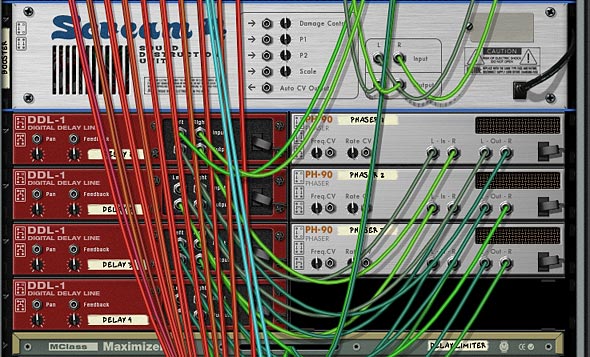
This Glitch Box uses 10 Malstroms to generate 10 different Glitch sounds, which are triggered by the Redrum Sequencer. The Redrum in turn has 32 patterns which are 64 steps each for a maximum Glitch mayhem. The interesting part of this patch is the way in which there are multiple Delay and Phaser units attached to the audio signal at the end. This creates a multi-tap delay effect which can be applied selectively.

Multi-Tap Delay setup (with Phasers)

Here is a rundown of how the Combinator Rotaries and Buttons work:

Pitch Wheel: This raises or lowers the pitch of the 10 Glitch sounds at once by +/- 7 semitones.

Mod Wheel:  This completely changes the type of sounds produced by the Glitch devices. Each Malstrom device was programmed to generate something totally wacky and off-the-wall when the Mod Wheel was used. So here is the result. Have at it!

Rotary 1:  Vocoder Filter – This Rotary affects the Thor Vocoder Modulation Filter. Use this knob to change the affect the filter has on the Vocoder. Basically, use this knob to dial in a sound filtering that appeals to you.

Rotary 2: Shift – This Rotary is used to raise or lower the “Shift” parameter of the Vocoder. Again, you’ll have to experiment with this knob to see what sounds best for you. You can also use it to create some interesting sweeps.

Rotary 3:  Pattern Sequencer – This knob allows you to select from 32 different Glitch patterns (all with 64 steps each). If you want to turn the patterns off, you can by turing the Rotary completely left (at zero). This turns off the patterns entirely so no sound signal will get generated.

Rotary 4:  Multi-Tap Delay – This adds some multi-tap delay effect to the glitch sounds. The Rotary acts as a dry/wet knob, so turning it fully left turns the delay off (dry), and turning it fully right turns it fully on (wet). Be careful as it’s easy to overdo it, and sometimes if other parameters are turned on (like Booster), the delay can get pretty loud. Though I’ve tried to limit the loudness of the delays with a Maximizer device. Just be careful not to overuse. 😉

Button 1:  Filter Type A/B – This changes the Thor Vocoder Modulation Filter from a simple Noise Oscillator to a different type of Noise Oscillator, and then adds in a Mixed sine Wavetable Oscillator into the mix. Try it out to change the sound entirely.

Button 2:  Bands 4/32 – This switches the Vocoder Band count from 4 (not pressed) to 32 (pressed in). Use this to keep the sound thin with 4 bands, or thicken it up with 32 bands.

Button 3:  Hold – This triggers the Hold button on the Vocoder. This can add some interesting unpredictible outcomes if pressed every so often. Or create a stutter effect by programming it to hold every bar, beat, or at random throughout your track.

Button 4:  Booster – This adds some emphasis and warmth to the sound via a Scream device.

Glitch Box 3 (Green – Subtractors)

This Glitch Box uses 10 Subtractors to generate 10 different Glitch sounds, which are triggered by the Redrum Sequencer, just like the other Glitch Boxes above. There’s 32 patterns which are 64 steps long, again like the other Boxes. There are a few interesting things happening in this patch, which I’ll go through one at a time.

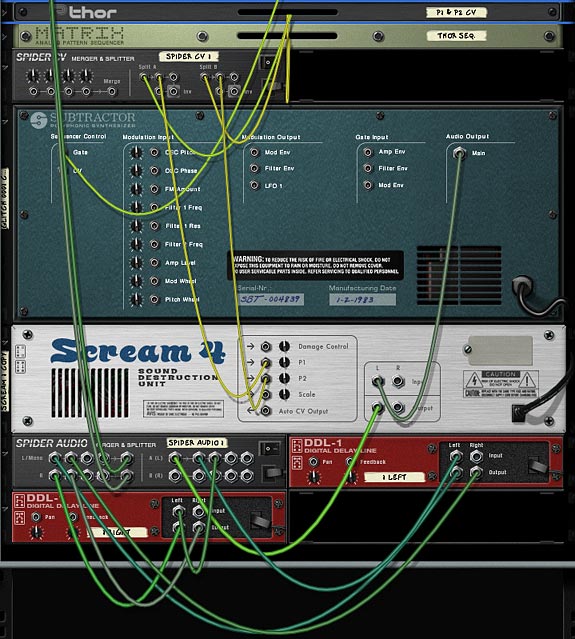
First, there are Scream Distortion units attached to each of the 10 sounds. The Screams are randomly sequenced to switch using the Matrix “FX Sequencer.” The Curve CV is cabled from this matrix to Rotary 4, which in turn is set to program all the Scream units to various degrees.

Second, there are two Digital Delay units attached to each of the glitch sounds. One unit is set up for the left, and the other for the right. Then they are merged together and sent back to the mixer. By changing the steps associated with each of these devices, you can set up some very complex delay patterns, which in turn enhances the “Glitch” element for each of the sounds.

The anatomy of a single Subtractor Glitch sound with Scream and Left/Right Delay FX

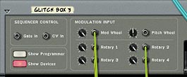
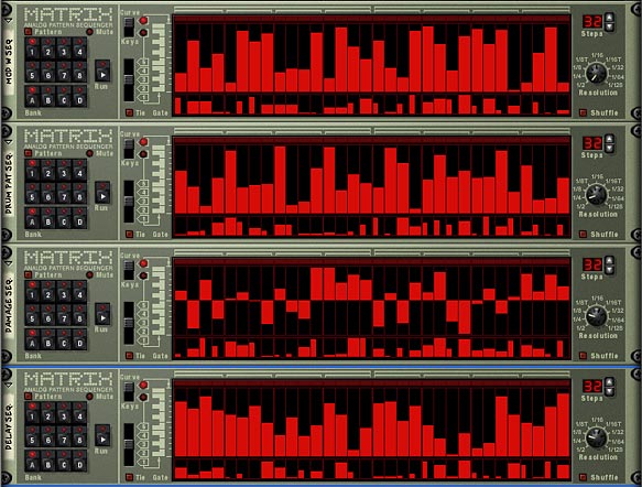
Third, Auto-Sequencing is set up so that there is an even more random element added to the box. Here, a matrix is set up for each Rotary as well as the Mod Wheel.

Auto-Sequencing the Mod Wheel and first 3 Rotaries. The fourth is controlled by the Matrix FX Sequencer.
The 4 Matrixes controlling the Mod Wheel, Pattern, Delay, and Scream Damage

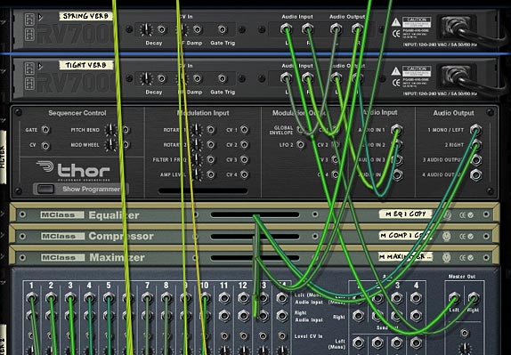
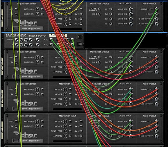
Fourth, there are a few other effects added into the Mix. If you’ve read some of the other articles, you’ll no doubt be familiar with ways in which the audio can be routed through Thor, and thereby use Thor’s filters on the audio signal chain. So I’ve added an alternate filter using this method. In addition, there are two Reverbs set up at the end of the signal chain in order to add a bit of room where the glitch sounds can feel at home.

Routing the Audio through a Thor Filter, as well as the 2 Reverbs

Fifth, and finally, The P1 and P2 parameters on the Scream devices are controlled via CV by a Thor device. The setup is that LFO1 controls P1, and LFO2 controls P2. So if you want to control these two parameters on every Scream device simultaneously, all you have to do is make changes to the LFO1 and 2 parameters in the Thor “P1 & P2 CV” device. This can help add some further Glitchy fun with the sound (especially when the Damage Type keeps changing randomly).

Here is a rundown of how the Combinator Rotaries and Buttons work:

Pitch Wheel: This raises or lowers the pitch of the 10 Glitch sounds at once by +/- 4 semitones.

Mod Wheel:  This affects a few of the Glitch sounds, but not too much. It’s pretty much unassigned.

Rotary 1:  Drum Pattern – This knob allows you to select from 32 different Glitch patterns (all with 64 steps each). If you want to turn the patterns off, you can by turing the Rotary completely left (at zero). This turns off the patterns entirely so no sound signal will get generated.

Rotary 2:  Delay Dry/Wet – This Rotary allows you to apply Delay to the Glitch sounds in a very random way (depending on how the steps are set up in each of your DDL devices. I can only recommend that you play around with the settings in these units, especially varying the steps on each unit). The Rotary acts as a dry/wet knob, so turning it fully left turns the delay off (dry), and turning it fully right turns it fully on (wet).

Rotary 3:  Damage Dry/Wet – This works the same way as the delay does (Dry/Wet), but this time the Scream’s damage knob is affected for all the Scream units. Be careful not to go too far overboard as you can end up making the sound pretty loud. I tried to limit it already a little bit by cutting off the amount of damage that can be applied, but it can still cause pretty loud signals. So just use it cautiously and always be on the lookout for your levels and clipping.

Rotary 4:  Glitch Hi <-> Lo – This essentially will turn off the amount of randomness applied to the Scream devices “Damage Type.” The way the Screams are set up, the matrix controls the damage type and randomly shifts from one type to another using CV to control this knob. If you keep it fully left, the Screams are at their most random; receiving switching cues from the matrix. When the knob is turned fully right, the damage type will not change at all and will stay fixed. So this Rotary controls how much randomness is applied to the Scream Damage Type, or rather how much switching between Damage Types will take place.

Button 1:  Spring Verb – This applies a spring reverb to the entire mix. Feel free to change the RV 7000 patch to anything that you feel suits this sound.

Button 2:  Tight Verb – This applies a tight reverb to the entire mix. Feel free to change the RV 7000 patch to anything that you feel suits this sound.

Button 3:  Comb Filter – This adds a comb filter to the entire mix to quickly change the Glitch sound. Feel free to change this in the Thor “Filter” device, if you like. It’s in the “Filter 3” slot.

Button 4:  Auto Sequence – This button applies a random auto-sequenced element to the Glitch box. It randomizes the Mod Wheel, and first 3 Rotaries (Drum Pattern, Delay, and Damage).

I hope this article provides a few new ways you can add to your Glitch fun in Reason. There’s probably a million different ways you can add Glitch into your tracks. I know Ed from EditEd4TV fame has just come up with a beat repeater that is quite amazing and interesting to look at. Visit the PUF (Propellerhead User Forum) for more information. And if you have any other ideas for ways in which you can make Glitch come to life in reason, please let me know. I’m always interested to hear about your techniques. Don’t be shy. Share them! And until my next installment, have fun in Reason and Record.

Cheers.

12 – Crossfading Mals & Filters

Since Ed’s Thor Shaper article, I’ve been thinking about how to use this information in real-world examples. One idea is to crossfade the Grain Samples in the Malstrom and another idea is to crossfade all 4 Thor filters to affect one sound source. Lots of fun!

Since Ed’s Thor Shaper article, I’ve been thinking about how to use this information in real-world examples. One thought came from a post I saw on the Props forum. Basically, the issue was that you can’t assign the Malstrom Grains to a Combinator Rotary to effectively switch between the 80+ Grain Samples. It’s pretty easy to assign and switch between Modulator waveforms using a Rotary, but not the actual samples in the Malstrom. So this got me thinking of how you could go about switching between these Samples. And truth be told, there’s probably some really obscure way to do it which uses Thor and some heavy CV connections. But here is something that might just inspire you and be the next best thing.

You can download the project zip file here: crossfading-malstroms-and-filters. This file contains 2 rns files with the Combinator setups explained below. One is a 16-Malstrom crossfader, and the other is a 4-way Thor filter crossfader. I would recommend you download them and open them up as you read. It will make things a little easier that way.

Crossfading 16 Malstrom Grain Samples

In this setup, I’m using 16 Malstrom devices and each device is sent to a Mixer Channel in two 14:2 Mixers. The CV from the various Thors are sent to the Mixer Levels, where the level trim knobs are pushed all the way right, and the Mixer channel Levels are set to zero. If you haven’t already seen Ed’s interesting and enlightening tutorial on the subject, you should read it here: Ed’s Thor Shaper Tutorial. It goes through using the Sine Wave Shaper in Thor to create a 4-way Crossfader. In this way, you can cross-fade between 4 different Malstroms. Each Malstrom’s Oscillator A is set to a different Sample.

Since you have 4 Rotaries, each Rotary is set to 4 Malstrom devices. Giving you a total of 16 different Oscillators. Also, since one or more oscillators will be playing at any one given time, I’ve set up each button on the Combinator to mute the specific series of Oscillators. Button/Rotary 1 affects the first group of 4 (Malstroms 1-4), Button/Rotary 2 affects the second group of 4 (Malstroms 5-8), and so on. Only 10 Malstroms should be applied to a single Mixer because you can only map 10 parameters from any one device to the Combinator, and you need all 10 channel mutes mapped to the various Combinator buttons.

To take this a step further, you could create 6 Combinators, which together would contain the full 82 Oscillator Samples used by the Malstrom. Then you could crossfade between any oscillator you like. The sweet spots for each of the rotaries are as follows:

0 = Oscillator 1 Full Level

42 = Oscillator 2 Full Level

85 = Oscillator 3 Full Level

127 = Oscillator 4 Full Level

Any integer between those values will provide a crossfade between the two Oscillators on either side of the value. This can be seen as a downside or an upside. If you want a pure switch between Oscillator 2 and 4 for example, you can automate the Rotary to go straight from 40 to 85 in your sequencer using a Rotary automation lane. In this sense, you can use the Rotary as a 4-way button switcher between each Oscillator.

On the downside, you couldn’t effectively crossfade between Oscillator 2 and Oscillator 6 (on Rotary 2) the way the current Combinator is set up. But if you Reorganize the way the buttons mute, you could effectively do this. I’m open to anyone who has any other suggestions on how this could be achieved. Another downside is that since a different Malstrom is used for each Oscillator, you’ll have to tweak the settings on each Malstrom to get exactly the sound you want. If you want to keep everything consistent between all Malstroms, you’ll have to do it through automation (the easiest way I think). Simply automate one parameter on the first Malstrom in the sequencer, and copy that automation clip into every other Malstrom’s automation lane. It’s a bit of a pain, but it will keep all Malstroms in line, if that’s what you want.

On the upside, since there are 16 different Malstroms, you can fine tune the sound of each of them separately. If you have all the mutes off, you can effectively crossfade between 4-8 Malstrom sounds/devices at once just by shifting the Rotaries around. This adds some very interesting Sound Layering potential.

As it stands, the first 16 Oscillators from the Malstrom are applied to the 4 Rotaries on the Combinator. As I said, you could build up a stack of 6 Combinators to include all the Malstrom Oscillators. In this way you can build up various sounds and switch between the various Oscillators. Does this help anyone out?

Crossfading all 4 Thor Filters, and then some. . .

Next, let’s take a look at how we can crossfade all of Thor’s filters to affect one synth sound. In this case, it’s fairly simple to set up. First, create a Combinator, and set up Ed’s 3 Sine Shaper Thor’s to handle the CV like the previous example (along with a 14:2 Mixer). Then create a Thor and load up a synth sound. Start off with something simple so that you can really hear the different filters affecting the sound. Then create a Spider Audio CV Merger / Splitter, and send the synth’s Left and Right Audio Outputs to the splitter’s inputs. Create 4 Thors underneath the splitter and send each of the 4 splits to these respective Thor’s Audio Inputs 1 and 2. Finally, send the 4 Thor’s Left and Right Audio Outputs to the first four 14:2 Mixer channels.

The setup with The Sine Shaper CV and Audio outputs from Thor into the Mixer
The Thor Synth Audio being split and sent through the 4 Thor Filters

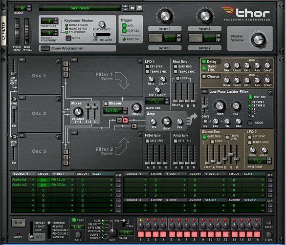
On the front of the Rack, add a Low Pass Ladder Filter in the first Thor’s Filter 3 Slot. The settings for this filter are shown in the image below. In addition, add the following into the Modulation Bus Routing System (MBRS):

Audio In1: 100 > Filt3 L.In

Audio In2: 100 > Filt3 R.In

The Low Pass Ladder Thor Filter settings on the front Panel

Enter the same settings in the other 3 Thors, but with different filters, so you have the State Variable filter in Thor 2, Comb filter in Thor 3, and Formant filter in Thor 4. While you’re at it, play around with the Global ADSR envelope so that it sounds to your liking for the 4 different filters. It’s ok if these settings are different for each filter. This will just make your sound more interesting. One thing I kept the same across all 4 Thor Filters is the FX section (Delay and Chorus). This way, when the filters are transitioned, the FX remain similar across the board.

Now let’s turn to our Combinator section and do some serious routings in the Mod Matrix. Here’s the settings you will need for each of the Thor Filters (they are the same for all 4, but must be applied to all 4):

Rotary 1 is reserved for the Filter Crossfade, so I’m not going to go over it here. You can see it in the Project File rns.

Rotary 2 > Filter 3 Freq: 0 / 127

Rotary 3 > Filter 3 Res: 0 / 127

Rotary 4 > Filter 3 Global Env Amount: 0 / 127

Button 1 > Delay On: 0 / 1

Button 2 > Delay Sync: 0 / 1

Button 3 > Chorus On: 0 / 1

Button 4 > Filter 3 Global Env Invert: 0 / 1

Mod.W > Filter 3 Drive: 50 / 127

The Combinator Mod Bus Routing settings for each of the Filters

Now, what’s happening is that the Mod Wheel controls the drive amount on each of the Filters, While Rotary 1 cross-fades all the filters. This is the main Rotary, and it has the same sweet spots as the previous Malstrom patch. Rotary 2 and 3 control the Frequency and Resonance of the filters, and Rotary 4 adjusts the Envelope of the filter. Button 4 inverts this envelope. The remaining buttons are left for the Delay, Delay Sync and Chorus. Since all the parameters are the same for all the filters, they all shift together. This can be a positive or a negative. You can’t individually set the filters, but at least they sound pretty good when transitioned. Depending on your ADSR settings for the Global Filter, the Envelope Rotary and Envelope Inversion Button may be different for each filter. But as I said before, this can add some nice variety to the sound.

Use this Combinator as a template for your own sounds. All you have to do is add your own patch into the Thor “Synth” or change the Thor “Synth” to any other Synth or Sampler device if you like. Then you’re in filter crossfading heaven.

A huge thanks to Ed for being the inspiration for these patches. Please let me know what you think and if you can think of any other applications that this crossfading technique can have, by all means share it with us. Until next time, have fun with these.

11 – Creative ReDrums (Part 3)

In this Tutorial, I’m going to show you a few other innovative things you can do with a Redrum device and a little imagination. First, we’ll build upon the drum kit we created in Part 2, and then branch out to show how you can chain your drums together and layer them to give a richer thicker sound. Finally, I’ll point out a few other quick and easy tricks, just to get your inspiration flowing.

In the first Part of this series, I showed you how to punch up your factory soundbank drums, and in the second, I showed you how you can create your own synth drum kit and trigger each drum via the Redrum device. In this Tutorial, I’m going to show you a few other innovative things you can do with a Redrum device and a little imagination. First, we’ll build upon the drum kit we created in Part 2, and then branch out to show how you can chain your drums together and layer them to give a richer thicker sound. Finally, I’ll point out a few other quick and easy tricks, just to get your inspiration flowing.

You can download the project files here: creative-redrums-3 The file contains two rns files with each of the Combinator setups outlined below.

Expanding on the “Electro Drums Combinator”

If you haven’t already, read Part 2 in the Redrum tutorials. After you’ve done that, you can start by downloading the Combinator I created or you can start with a Combinator that you’ve created yourself, because I know you want to stamp your name on your own sounds right?

  1. If you’ve done everything according to spec, you’ll have a pretty expansive drum kit which is filtered through a Vocoder. Now we’re going to change a few of the routings and Combinator mod matrix settings in order to put a new spin on that drum setup.
  2. Open up the Combinator and create a 6:2 Line Mixer at the top of the stack. Reroute the Vocoder Carrier outputs to the second channel of the Line Mixer. This is going to be our “Wet” signal. At the same time, connect the Left and Right Audio Out cables from the Line Mixer, and feed them into the Compressor’s Left and Right Audio inputs. Then connect the Left and Right Audio outputs from the Maximizer into the Left and Right Audio inputs on the Combinator (From Devices). So the signal path goes from the dry signal through the Vocoder, then into the Main Line Mixer, then into the Mastering devices, and finally out of the Combinator.
  3. Next, we’re going to add a “Dry” drum submix which can in turn be mixed in with the wet submix. To do this and also to have full control, we’ll need to create a whole new secondary mix. The easiest way to do this is to duplicate the 14:2 Drum Submixer, and holding Shift down, create 10 Audio Merger/Splitters underneath. Flip the rack around and connect each of the Synth Drum outputs (the Thors) into the Splitter inputs. Then use one split to go to the Wet Drum Submix channels, and a second split to go to the Dry submix channels. This is a bit of a process but it’s an important one as you’ll see in a minute.

    Routings from the back of the two Submixers
    Routings from the back of the two Submixers
  4. Now route the entire “Dry” Submix (Left and Right outputs) to the first channel in the main Line Mixer (Left and Right inputs). Flip the rack around and click the “Show Programmer” button on the Combinator. In the Modulation Matrix, remove the “Master Level” settings we previously mapped to Rotary 4. Instead, select the “Main Line Mixer” on the left, and enter the following settings:

    Rotary 4 > Channel 1 Level: 0 / 127

  5. Now when Rotary 4 is fully left, the signal is fully wet. When the Rotary is fully right, the dry signal is mixed in with the wet signal. Furthermore, if you want to fine-tune the levels of either the Wet or the Dry drums individually, you can set that up using the levels on either submixer, giving you total control over both your wet and dry drums’ attenuation. If you want to automate the process, create a sequencer track for both the Dry and Wet Submixer and go ahead and automate the levels to your heart’s content.

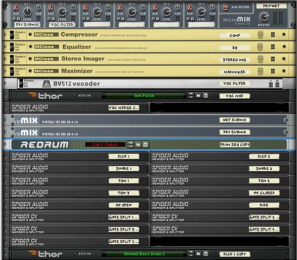
    Rack devices in the Combinator above the main synth drums
    Rack devices in the Combinator above the main synth drums

Note: In the Combinator I created inside the Project files, I also added an “Instant Glitch” and “Bass Boost” button which can be used to give the drums a completely new feel. I wouldn’t use them together, but separately they can open up a whole new way to play this patch. Also, there’s some other modifications I made to the original drums. I added a Vocoder Bypass switch on button 4, so if you are bypassing the Vocoder, there’s no need to mix in the dry signal, as the signal is already completely dry. So if bypassing the Vocoder, keep Rotary 4 fully left. Otherwise you’ll be doubling the dry signal which may not be desired. And lastly, I mapped Rotary 1 to the Stereo Width, so turn it fully left to create a pseudo-mono effect, and fully right to widen up the stereo field.

The front Combinator Controls

Chaining 2 or More Redrums Together

Another thing you can do with Redrums that can amplify and expand your drum programming is to Layer your drums by chaining them together. Whether you use Redrum patches for your drum sounds, or create a sample-based drum kit and have the Redrums trigger the synths, you can still create layered drum Combinators very easily. Here’s one method to do this.

  1. First create a Combinator and holding Shift down, create the following devices in sequence: M Class Compressor, M Class Equilizer, M Class Stereo Imager, M Class Maximizer, RV 7000 Reverb, 14:2 Line Mixer, 3 Redrums, and 2 DDL-1 Delay units.
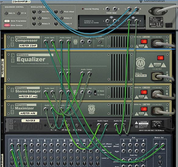
  2. Flip to the back of the rack, and Connect the Left and Right Mixer outputs to the Compressor’s Left and Right Inputs. Then chain the Compressor to the Equilizer to the Stereo Imager to the Maximizer to the RV 7000 and then out to the Left and Right Combinator inputs (From Devices). That essentially sets up the Drum Mastering.

    Routing for the Mastering in the Combinator
    Routing for the Mastering in the Combinator
  3. Connect the Left and Right Outputs from the first Redrum to the first channel on the Mixer. Connect the second Redrum’s Left and Right Output through the first DDL-1 unit and then to the second channnel on the Mixer. Connect the third Redrum’s Left and Right Outputs through the second DDL-1 unit and then to the third channel on the Mixer. This sets up our Redrum Audio channels.
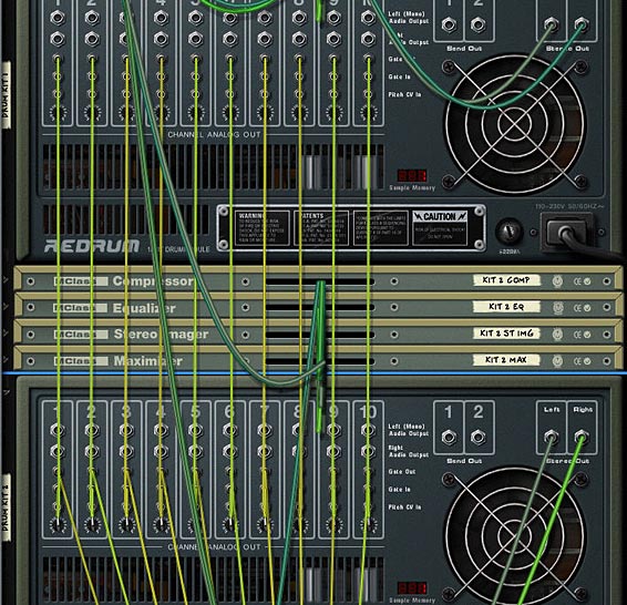
  4. Lastly, send the Gate Out CV for the first Redrum’s first channel to the Gate In CV on the second Redrum’s first channel. Then send the Gate Out CV on the Second Redrum’s first channel to the Gate In CV on the third Redrum’s first channel. Repeat this process for all 10 Redrums’ channels. This way, the first Redrum acts as the “Master” Gate triggering the other two “Slave” Redrums in Parallel (actually this is in series, but the effect is that all three Redrums trigger at exactly the same time, which is why we’ve inserted a Delay unit between the last two Redrums and the Mixer).

    CV routing between the "Master" (Gate Out) and "Slave" (Gate In) Redrum
    CV routing between the "Master" (Gate Out) and "Slave" (Gate In) Redrum
  5. Flip the rack around to the front. Bypass all the M Class devices as well as the Reverb and Delay devices for now. Add patches into the three Redrum devices so that you have different drum kits in all three. Then disable the pattern section on the two Redrum Slaves (last two Redrums). Add a pattern into the Redrum Master (the first Redrum — simply select the device, and click Ctrl+R to get a random pattern entered). Then press the Play button and you’ll hear all three Drum kits working the same pattern at the same time. This is your basic setup.
  6. Next, turn On the Delay units and enter some step sequence that sounds good for the second and third drum kits. This is a matter of taste, but if you look at my Combinator file, you’ll see I have the second Redrum’s delay set to 3 steps and the third Redrum set to 6 steps. I also adjusted the levels and Panning of all three drum kits in the Mixer so that it didn’t shatter my speakers and start giving me that beautifully annoying red clip light (Note that I also added a Scream 4 unit between the third drum kit and its associated Delay line. That’s because the drums from the third drum kit sounded a little lacking). By delaying two of the three drum kits you end up with a much fuller sound. However, this can be a bit of overkill as well. If you like, try tuning the Dry/Wet knobs on the delays so that the delay is a little more subtle. Again, it’s all a matter of personal taste.
  7. Finally, adjust your Compression, EQ, Stereo Imaging, and Maximizing using the M Class Devices. What’s more, you should experiment by using separate M-Class devices for each of the Redrum kits and adjust them independantly. In this way, you can have a greater degree of control over the final sound. In fact, if you want to go all out, you should create four sets of M Class devices; 1 for each of the drum kits, and one for an overall mixdown of the three drums together. This can help to really bring the drum mixes together.

The whole idea here is to choose drum kits that work well together and don’t clash. They should compliment each other. Some ways to ensure they are complimentary is to choose drum patches in the same or similar vein (all Dub kits or all Electronic kits). Another way is to EQ each drum kit so that it has its own place in terms of frequency. A third way is to pan them and mix their stereo width so that they also have their own space within the stereo field. This, of course is beyond the scope of the tutorial, but it’s all a matter of your own personal taste. Keep experimenting!
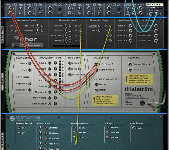
If you look at the Combinator Mod Matrix, you’ll see that I’ve mapped the second rotary to the pitch of all 30 drums in the 3 Redrum devices. This is a great way to quickly change the pitch of all the drums in the Combinator. The downside is that since you use 10 routings per device in the Mod Matrix, you lose the ability to map anything else from the Redrum devices to the Combinator. So I’ve opted to show you how to map the pitch to the rotary instead of mapping the pattern sequencer to a Rotary control. However, if you want to automate the Pattern Sequencer from the first Redrum, simply create a sequencer track for the Redrum, then automate your patterns directly in Reason or Record’s main sequencer. A few more clicks, but it’s still fairly easy to program.

Where do you go from here?

This is definitely not the end-all-be-all when it comes to the Redrum. There’s a lot more you can explore, such as mapping some of the other parameters to the Rotaries, for example the drum level knobs, or the main Resolution knob. You can also automate pretty much every element of the Redrums in the main Sequencer. In addition, you can layer your own synth sounds on top of each other to create some pretty massive synth drum kits. Hopefully this at least gives you a few new ideas when it comes to programming your drums. I know after 3 tutorials on the subject I’m done working on the Redrum for a while. Time to get back to working on some synths again.

So do you find these setups useful? Do you have any setups that you’d like to share? I’d love to hear about them. Feel free to comment and let me know. And thanks for taking the time to read these tutorials. Your feedback and comments are very much appreciated.

10 – Creative ReDrums (Part 2)

In part 1 of our Redrum tutorials, I showed you a few ways you can improve the drum kits in your arsenal by using Thor’s filters, and some M Class Mastering devices. In this tutorial, I’m going to work in reverse and show you how to use the Redrum as a gate CV device to trigger a series of 10 Thors, which act as the drum sounds.

Creative Redrums (Part 2)

In part 1 of our Redrum tutorials, I showed you a few ways you can improve the drum kits in your arsenal by using Thor’s filters, and some M Class Mastering devices. In this tutorial, I’m going to work in reverse and show you how to use the Redrum as a gate CV device to trigger a series of 10 Thors, which act as the drum sounds. This is where things can get pretty interesting, as you can gain complete control over the drum sounds by creating them from scratch using Thor’s Oscillators and Filters. Then, we’ll try to use a technique laid out by Matt Piper in which all the drums are filtered through a Vocoder. This is yet another way to get some beef and boom out of the drums. So let’s work some creative Redrum magic.

The project file contains an .rns file with a single Combinator which outlines a complete drum kit with vocoder filtering, Mastering, and a few extra effects thrown in. Download the Project Files here: creative-redrums-2.

The Basic Setup

  1. Create a Combinator, and inside create a 14:2 Mixer. Then holding Shift down, create in order a Redrum, Spider CV Merger/Splitter, and Thor Synth.
  2. Right-click over the Redrum Pattern section and select “Randomize Pattern” just to quickly add a pattern. For this tutorial, the Redrum is used as a sequencer, and nothing more. You’ll be able to change the Resolution of the Pattern, number of steps, and use the Mute/Solo functions, but samples are not necessary.
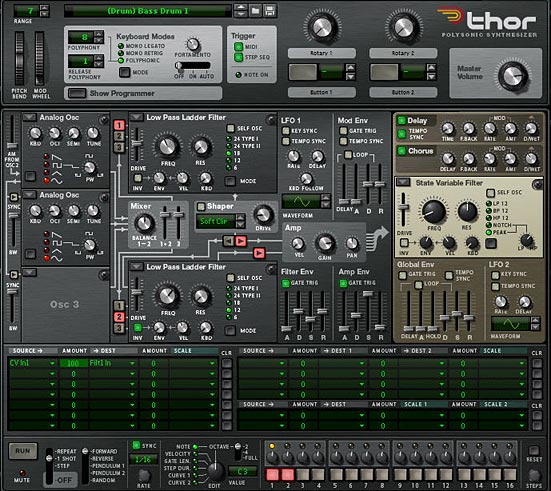
  3. Next, Create a Bass Drum sound in Thor. Here’s an example of one way you could go about doing this (see the screenshot below). In the Sequencer section, change the Run Mode to 1-shot, and reduce the steps down to 2. Then in the Modulation Bus Routing Section (MBRS), enter the following:

    CV In1: 100 > Filt1 In

    The Front Panel of Thor with our Analog Bass Drum Sound
    The Front Panel of Thor with our Analog Bass Drum Sound
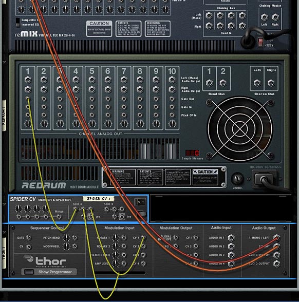
  4. Now let’s flip the rack around to the back and make our routing connections. First, connect the Left and Right Audio Outputs (1 and 2) from Thor into the Left and Right Audio Inputs on Channel 1 on the Mixer. Then connect the Gate Out on Channel 1 of the Redrum into the Split A input. Send one split output to the CV 1 In on Thor, and send another split to the Gate in (Trig) CV input on the Thor Step Sequencer (at the bottom of Thor).

    Routings on the Back of the rack
    Routings on the Back of the rack
  5. Press Play, and if you will hear the Bass Drum playing. If you don’t hear anything, be sure to check the Pattern in the Redrum and make sure there are some Bass Drum parts in the Pattern Sequencer.
  6. Still on the back of the rack, select the Spider Merger/Splitter and Thor together by shift+clicking on both devices. Right-click and select “Duplicate Devices and Tracks.” Then connect the Left and Right Audio Outputs (1 and 2) from the second Thor into the Left and Right Audio Inputs on Channel 2 on the Mixer. And connect the Gate Out CV from the Redrum second channel into Split A on the Spider CV Merger/Splitter.
  7. Flip the rack around to the front and create a new drum sound in Thor, maybe another Bass Drum or Snare. Repeat this process until you have all 10 Redrum channels filled up. Congratulations! You’ve just created a complete drum kit.
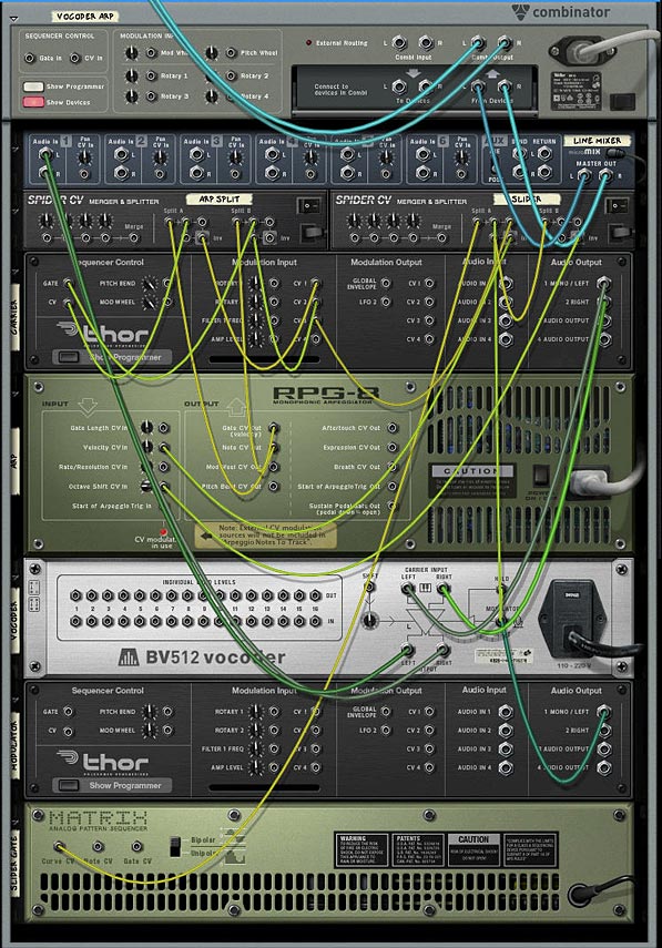
Vocoder Filtering

This trick was shown in Matt Piper’s great Youtube video where he set up a Vocoder to filter his drums. To see the video, visit his tutorial here: propellerhead-record-reason-vocoding-with-drums

  1. Once you have your drum kit set up, go to the back of the rack, and select the Mixer. Hold Shift down, and create a BV512 Vocoder, Thor, and a Spider Audio Merger/Splitter.
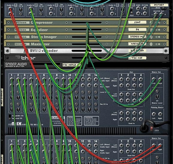
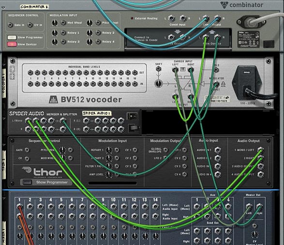
  2. Move the Left and Right Audio input cables on the Combinator (From Devices) to the Left and Right Carrier Input on the Vocoder. Then connect the Left and Right Carrier Output from the Vocoder to the Left and Right Audio input on the Combinator (From Devices).
  3. Route The 1 Mono/Left and 2 Right Outputs from the Thor device to two Left Merge channels on the Spider Audio Merger/Splitter. Connect the Merged output from those two cables to the Modulator Input on the Vocoder. With our routing set up, flip around to the front of the rack.

    Vocoder Routing setup
    Vocoder Routing setup
  4. On the front panel of the Vocoder, set the Band Count to 4 Bands (I also found the 8 and 16 bands work well, depending what kind of sound you are looking for). Move the Shift knob to around -24, and Decay to around 80.
  5. In Thor’s global top panel, set the Polyphony to 1, Release Polyphony to 0, and Key Mode to mono Retrig. In the Voice section, add a Noise Oscillator in Slot 1, set the Noise Wave to Color, and Noise Mod to around 36. Then turn on “1” to send the Oscillator to Filter 1 slot (which is on Bypass by the way). Turn off everything else except the Filter and Amp Envelope. In the Step Sequencer section, set the Run Mode to Repeat.

    The front panel settings for the Vocoder and Thor Modulator
    The front panel settings for the Vocoder and Thor Modulator

That’s really all there is to it. Not too complex, just time consuming to create all your drum sounds in the various Thor devices. But it’s very rewarding when you have your own custom drum kit set up just the way you want.

Where do you go from here?

  • You can try the same setup with a stack of Subtractors or Malstrom devices, or any combination of Subs, Mals and Thors to create your custom drum kits.
  • You can add a reverb and a delay to your drums. Also, for an instant doubling effect, you can modulate a button on the combinator to switch from 1-2 steps in all the Thors at once. This doubles up the drum beats (see below for this setup in my own Electro Drum kit).
  • Try going into the Thor which is used as the Vocoder’s Modulator, and switch the Oscillator 1 Noise wave from Color to Static, and then set the Noise mod dial to around 30 or so. You’ll create some very interesting glitch effects.
  • As you can see I’ve added a few effects here and there. There’s two phasers tied to the Hi Hats, for example. In this same way, you can chain some effects into the drums individually. Try adding some scream or even vocoding the drums separately. However, if you do, you’ll have to realize that the more effects, the more CPU intensive this gets. As it is, I only saw 2 bars on my CPU meter. Not too bad. Definitely less intensive than the last kit I put together.

Electro Drums Combinator Controls

Pitch Bend: Unassigned.

Mod Wheel: This controls the Band Count on the Vocoder from 4 bands (no modulation) to FFT (512) when pushed all the way up.

Rotary 1: Voc Filter – This controls the Noise Mod from the Vocoder’s Modulation Oscillator. This can be used to shape the sound of the Drum Filtering through the Vocoder.

Rotary 2: Shift – This controls the Shift parameter on the Vocoder. Again, this can be used to sculpt the sound of the Drum’s Vocoder Filter.

Rotary 3: Pattern Seq. – This knob is used to switch between all 31 patterns in the Redrum. You can assign any patterns you like in the redrum and it will be tied to this knob. In this way, when you’re playing the drums, you can switch on the fly. In my drum kit, I threw in a bunch of random patterns so that you can hear something playing no matter where the knob is set. Note that if the knob is turned fully left, an empty pattern plays (essentially turning the Pattern Sequencer off and silencing all the drums). This is good if you need an empty spot in your song.

Rotary 4: Master Level – This controls the master level of the Submixer, so that you can adjust the drum level globally.

Button 1: Doubler – This doubles all the drum beats via the Thor Step Sequencers. When on, the steps are set to 2, which will play two beats anytime the drum is triggered. When off, only one drum beat will occur when the drum is triggered.

Button 2: Alt Filter – This quickly switches the filters used to modulate the Vocoder, as well as adding a Scream and Reverb effect to the drums. I wanted to make this drum template as versatile as I could, so I thought why not add a completely different sound in the Combinator for some fun. It gives the drum sounds a completely different and more electronic (less organic) sound.

Button 3: Master Bypass – This button controls the Mastering (M Class) devices, as well as the Vocoder filter. If you don’t want to add any mastering or Vocoder Filter to the drums, turn this button on. The Drum sounds are then completely dry (or as they originally sound via the Thors). Leave it off if you want the drums compressed, EQ’d and Vocoded.

Button 4: HH FX – I added some Phaser FX to the High Hats just to give them a different feel. You’ll just have to try it out and see if you like it. I thought it was a cool sound, so I kept it in there as an option for you.

So let me know what you think of this setup, and if you have any other ideas or have some great tips for drum creativity, please feel free to share your comments.

Good Luck!

9 – Creative ReDrums (Part 1)

I decided to try out some Redrum creativity by taking a standard Redrum patch from the Factory Sound Bank and punching it up. At the same time, I tried to get creative with the Filtering and Routings. A new way to use your Redrum device.

I often get asked and see on the Props forum many complaints that the supplied drum kits are lacking in depth and sound flat. Often this takes the form of slams against the props for providing lacklustre drum kits in the Factory Soundbank. Truth is, the drum sounds can be expanded upon, and if you’re willing to take some time, they can be made to sound much deeper and more punchy. It’s all in what you do with them. The power is all there in front of you, and with the Redrum there’s a lot of flexibility.  

With this in mind, I decided to try out some Redrum creativity and put together a flexible drum kit that takes a basic kit from the props and turns it into something unique . There’s two things I want to accomplish with this tutorial: First: Create a Drum Kit that is more expansive sounding, and Second: Find some creative ways in which the Redrum can be used. So let’s see how far we can take it.  

Before jumping in let me first say that this template is fairly massive. It contains a lot of Thor filters, and as such it can be a little expensive on CPU. If you find it taxing your CPU, you can scale it down (see my notes in the “Where do you go from here” section below), or you can bounce it to an audio track to be put into a Dr. Rex device or as a separate audio track entirely. Second, there’s two main ways I find can bolster the sound of your drums: Compression/Mastering, and Filtering the drums, so those methods will be explored below.  

Download the Project files here: creative-redrums. The project files contain two Combinators inside an rns file. The first Combinator is the Original untouched kit put through the same Matrix sequencing. The second Combinator is the Drums we’re going to create below. Mute/unmute the channels in the mixer to listen to how they sound compared to one another.  

  1. As with all great Reason patches, let’s start by creating a Combinator. Inside the Combinator, create in order, an M Class Compressor, M Class Equilizer, M Class Stereo Imager, M Class Maximizer, 14:2 Mixer, Redrum Drum Machine, Thor Synth, DDL-1, and Spider Audio Merger/Splitter. Then hold Shift down and create a Matrix Pattern Sequencer.
  2. Flip the Rack around and let’s start working on our Routings. First, move the Cables from the Combinator’s “From Devices” ins to the Audio Inputs of the Compressor. Then connect the Audio Outputs from the Maximizer to the “From Devices” inputs on the Combinator. This sets up the main mastering for the Redrum.

    The Mastering setup on the back of the rack
    The Mastering setup on the back of the rack
  3. Next, move the DDL 1 Left and Right input cables to the Left and Right Channel 1 on the 14:2 Mixer. At the same time, disconnect the Chaining Aux cables from the 14:2 Mixer. Also, connect the Left output from Channel 1 on the Redrum to the Audio In 1 on the Thor. Then connect the Right output from Channel 1 on the Redrum to the Left input on the DDL-1.
  4. Next, move the Left and Right Audio Inputs from Channel 2 on the Mixer to two Left Audio Inputs on the Merger side of the Spider. Then route a cable from the Left Merged Output to Audio In 2 on Thor. With this setup, you’ll have no delay on the Left audio channel for the drum, while the Right Channel goes through the delay device.
  5. Moving to our CV routing, plumb a CV cable from the Gate CV output of the Matrix to the Gate In on Channel 1 on the Redrum. And plumb a CV cable from the CV 1 Output on the Thor to the Pitch CV In on Channel 1 of the Redrum. Also cable the Note CV output from the Matrix to the CV 1 Input on the Thor, and the Curve CV output from the Matrix to the CV 2 Input on Thor. If this is all starting to get confusing for you, check out the routings in the Combinator file download, or else check out the image below.

    The routings for the Thor Filter, Delay, and Matrix Sequencer
    The routings for the Thor Filter, Delay, and Matrix Sequencer.
  6. Next, let’s flip the rack around and start working on applying settings to the front of the devices. First, click the “Enable Pattern Section” button on the Redrum so that the pattern is disabled. Click the browse button and load a patch (drum kit) into Redrum. I used the Chemical Kit 7 from the Factory Soundbank (under Redrum Drum Kits > Chemical Kits). Now you have a basis from which to work.
  7. In Thor, we’re going to use multiple filters which will be applied to the Bass Drum (Channel 1 on the Redrum). So the first thing to do is to ensure that the Bass Drum Left and Right channels are routed into Filter 1 and Filter 2. In the Mod Matrix, apply the following settings:

    Audio In1: 100 > Filt1 In  

    Audio In2: 100 > Filt2 In  

    This setup means that the Left (dry) Channel goes through Filter 1, while the Right (delay) Channel goes through Filter 2, and then both are sent in Stereo to be output to the Submixer. 

  8. Next, since Thor is not free running, like the Subtractor, we need to use the step sequencer to keep Thor “On.” To do this, set up a one step long pattern in the sequencer. Turn Button 1 on (so it’s Red) on the top panel of Thor. Then add the following setting into the Mod Matrix:

    Button1: 100 > S. Trig  

    To be honest, since everything will be triggered when you hit the play button, you probably don’t need to setup the above (step 8). But it will ensure that Thor remains on and is running, which will ensure you can use the filters in the Voice section of Thor (the first two filter slots), as well as the Global filter section (Third Filter slot).  If I’m wrong, please feel free to correct me.

  9. Add a Low Pass Filter into Filter slot 1, and a Formant Filter into Filter slot 2. Route both the filters parallel into the Amp section of Thor. Turn off any Oscillators and Oscillator routings, as well as the Mod Envelope and Global Envelope sections. And Then add the rest of the MBRS settings as follows:

    CV In1: 100 > CV Out1 (sends the Note CV data from the Matrix to the CV Pitch in on the Redrum Channel — yes you can send the CV cable directly from the Matrix to the Pitch In on the Redrum, but If you set it up this way, you can then use the Note CV to affect other parameters in Thor, if you wish).  

    CV In2: -75 > Filt1 Freq (sends the Curve CV data from the Matrix to the Filter 1 Frequency).  

    CV In2: 75 > LFO 1 Rate (sends the Curve CV data from the Matrix to the LFO 1 Rate).  

    LFO1: -46 > Filt2 Y (sends the LFO 1 to the Filter 2 – Formant Filter – Y Parameter).  

    Here’s the image which shows the front of the Thor Device and the Filter settings:  

    Thor settings for the main Bass Drum Filtering
    Thor settings for the main Bass Drum Filtering
  10. Next, on the DDL-1, select 4 Steps, and in the Matrix, create a Random pattern. Alternately, you can build your pattern as you play the sequence. The Matrix will trigger the Drum’s Channel 1 gate, and play the pattern you enter. So it can be much easier to build up a drum pattern as you play. Also, as you play, adjust the filter settings in Thor until you come up with your own unique brand of Drums. At the same time, flip the rack and adjust the Pitch In Trim knob on the Redrum Channel 1 to taste.
  11. Now comes the tedious part. Select the Thor, DDL-1, Spider Audio Merger/Splitter, and Matrix. Then right-click and select “Duplicate Devices and Tracks.” Once duplicated, flip the rack around to the back of the devices, and set up the routings into the second Channel of the Redrum and Submix (along with the CV routings, etc.). Do this for each Channel of the Redrum.
  12. Once everything is routed properly, you can start to work on filtering each individual drum channel. Try out different Thor filters, as well as different Matrix patterns (right-clicking and using “Alternate Pattern” works well here, along with shifting the patterns left or right). Also try alternating some of the delay routings from left and right (by reversing the audio inputs on the back of the Thor. Finally, try out different delay steps for each of the delays. There’s lots you can do to fine tune this type of setup.

Combinator Mod Matrix

Going into all the modulations in the Combinator is pretty intense, so instead I’ll let you download the project files and see what’s going on. But a few words about how the Rotaries/Buttons work:  

The Pitch Bend moves all the drum pitches up or down. This can be fun to play with while performing with the drums. The downside is that when the Pitch Bend is static center, so are all the drum pitches. But you can always automate it so that it stays in a non-static, non-centered position.  

The Mod Wheel is tied to a basic drum Reverb which also affects all the drums equally. If you don’t like this Reverb, you can use your own. This way you can apply a little or a lot of Reverb to the overall mix. And then of course there’s nothing saying you can’t add a Reverb or other FX as Send FX on the Submixer. This was a last-minute thought.  

Rotary 1-3: Applies Compression, EQ, and Maximizer Gain to the overall mix. In this way you can master the drums to your liking.  

Rotary 4: Affects the Delay Levels for all drums at once. You can go from no delay (at the far left) to a pretty heavy delay (on the far right).  

Buttons 1-3: Turns on/off the delays for the Bass Drums (1), Snare Drums (2), and High Hats (3).  

Button 4: Turns on/off the Ride by muting it on Channel 10 of the Submixer.  

Where do you go from here?

  • Add different variations and drum patterns (fills and rolls) in the Matrix pattern sections. Then create sequencer tracks for all the Matrixes. In this way you can play the patterns for each of the drums in their own separate tracks on the sequencer, and they are all pattern-based. This makes creating several variations very easy not only to explore, but also to apply in your song.
  • If things are a little too chaotic having all 10 drums running at once, simply mute some of them in the Drum Submixer, so let’s say you have a Bass Drum, Snare, and Hi Hat instead of an all-on cacophony of drums.
  • At the same time, if the CPU load is a little too much, try minimizing the number of filters used, and instead run each drum channel through only one filter, instead of two. Or delete the drums you aren’t using, along with their associated Thor/Delay/Splitter/Matrix.
  • Once you have this template built (and you already have mine done for you), you can add different drum kits into Redrum, and adjust settings for your filters, mastering, etc. One thing that helps is to work on the drums in a build-them-up-as-you-go way. So first do the Bass Drum, then mute the bass drum and go on to the Snare, then unmute and see if they work together. Once they do, move on to the next drum.

And no more than a few days after I posted this article, Matt Piper posted a great little youtube tutorial on how to process your drums through a BV512 Vocoder. You have to check it out. It sounds awesome. Great inspiration for those that want another way to beef up your drum kits: propellerhead-record-reason-vocoding-with-drums

So let me know what you think of this setup. Do you know of some great methods for getting more out of the drum sounds provided in the Factory Soundbank? Do you have any creative drumming techniques. Please feel free to share them. I’d love to see what can be done to boost the supplied drums and learn some new creative ways to ReDrum the kits. Good luck in your Reason projects!

8 – Auto CV (Chasing Audio)

Learn how to use the Scream’s Auto CV output to convert an audio signal into a CV signal. Also learn how Thor can be used to achieve a similar effect, and how you can use Thor to switch between different CV sources.

We don’t live in a vacuum (well maybe sometimes we do, however, for the most part we learn by experimenting with many different elements from different sources) and so this tutorial will build upon a previous tutorial on using Thor’s CV capabilities to switch between 2 different CV sources. In addition, there will be a new element which shows how the Auto CV on the back of the Scream can be used to follow the audio from a Dr. Rex. And this is really the heart of the tutorial.

The “Auto CV” feature on the back of the Scream device is an envelope follower with a twist. While most envelope followers work on Audio and in essence shape the parameters of the audio, the Scream’s envelope follower follows the audio, and then converts that to a CV signal. Before Reason 4, this was the only way you could essentially create a CV signal from an audio source. With the advent of Reason 4, you can use Thor to perform the same functions. Even so, it’s worthwhile to note how the Auto CV works in the scream, as it can still be used effectively, with the added bonus that it leaves a lighter CPU footprint, and allows you access to the Scream as an FX insert as well. Finally, I’ll touch upon how you can achieve a similar effect using Thor.

The project files can be downloaded here:  auto-cv-chasing-audio It contains three Combinators which are used as examples to show the Auto CV setups described below. A matrix is used to play a random pattern so you can hear the results. All Combinators play simultaneously through the main mixer, so don’t forget to mute or unmute the channels to hear the proper example.

Using the Scream Auto CV to convert Audio into CV

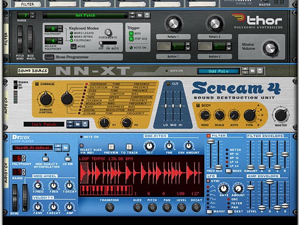
  1. Create a Combinator and a 6:2 Line Mixer. Then holding shift down, create in order a Thor, NN-XT, Scream and Dr.Rex device.
  2. Click the Show Programmer button in Thor, and turn off Oscillator 1, Bypass Filter 1, and click the “1” button next to the Filter 1 slot. Add a Low Pass Ladder Filter in the Filter 3 slot. Finally, click the Delay button to turn on the Global Delay.
  3. In the NN-XT open up the patch browser and navigate to the Factory Soundbank. Go to the NN-XT Sampler Patches > Synth Poly and open the Odd Poly patch.
  4. In the Scream device, turn off the “Damage” parameter.
  5. In the Dr.Rex device, open the Patch browser and in the Factory Soundbank, nagivate to Dr Rex Drum Loops and load the Hse40_RideBeat_130)eLAB.rx2 patch.
  6. The Front of the Rack with all Devices necessary to chase your audio
    The Front of the Rack with all Devices necessary to chase your audio
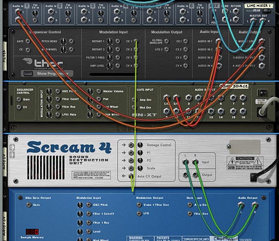
  7. We’re done with the front panel. Flip to the back of the rack, and let’s move on to routings. First, route the NN-XT’s 1/L and 2/R to the Audio In 1 and Audio In 2 on the Thor Audio Inputs, respectively. Then route the 1 Mono/Left and 2 Right from the Thor’s audio outputs to Channel 1 on the Line Mixer (left and Right, respectively). This sets up the audio to be heard. Now comes the Auto CV magic.
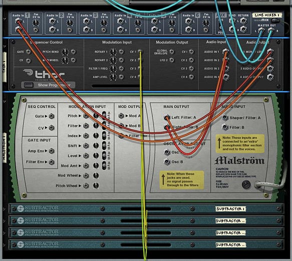
  8. In order for Auto CV to work, the Scream needs to have a sound source fed into it. So connect the Dr.Rex L & R audio outputs into the Scream Audio Inputs (L and R, respectively). Then connect the Auto CV output from the Scream unit into the CV 1 Modulation input on Thor.
  9. Auto CV routing to follow the Rex Audio file via CV
    Auto CV routing to follow the Rex Audio file via CV
  10. Flip the rack around and let’s set up the Thor Modulation Bus Routing Section (MBRS). Enter the following parameters on the left side of the bus:

    CV In 1: 66 > DelFBack

    CV In 1: 66 > Del ModAmt

    Enter the following parameters on the right side of the bus (just to keep things simple for now):

    Audio In1: 100 > Filt3 L.In

    Audio In2: 100 > Filt3 R.In

  11. The MBRS settings in Thor
    The MBRS settings in Thor
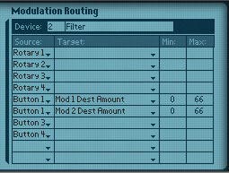
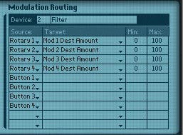
  12. With this setup, the Auto CV is affecting the Thor Delay Feedback and Delay Modulation Amount. To hear what the Scream is actually doing, we can set up a Combinator switch on button 1. So click the Show Programmer button on the Combinator, and click the Thor in the Device section of the programmer. Enter the following two lines in the Modulation Routing section:

    Button 1 > Mod 1 Dest Amount: 0 / 66

    Button 1 > Mod 2 Dest Amount: 0 / 66

    Programmer Modulation Routing in the Combinator
    Programmer Modulation Routing in the Combinator
  13. Now set up a Matrix to play a simple pattern using the Combinator. Turn Button 1 on to hear the Auto CV affecting the Delay. Turn it off to hear the unaffected Delay. Note that you need to have the Dr. Rex receive notes in order to have it send audio into the Scream device. By setting up the Matrix to sequence the combinator, the matrix ends up playing the Dr. Rex. So you’re all set. Alternately, if you don’t want the matrix sequencing the Combinator, you can always copy the Rex notes to its sequencer track so that the Dr. Rex is played via the main sequencer. The point is, the Dr. Rex needs to be active.

What’s happening is the Dr.Rex loop is converted to CV, and this CV is used to affect the Thor Delay. It’s a simple but powerful setup. And you don’t have to limit yourself to affect Thor parameters. I only used this as an example. You run any audio source through the Scream and then use the Auto CV to affect any other CV parameter. Also, since the Scream is not generating any audio output, it doesn’t affect the mix in any other way than a simple CV conversion (or more technically, a CV envelope follower).

Switching CV sources

Not to be one to leave well enough alone, here’s a way to extend the Auto CV idea above and have the ability to switch between two different Rex Files (2 CV sources) using the Thor. The parameters affected are the same (Delay Feedback and Delay Modulation Amount), but the Rex file used to affect the delay can be switched. Here’s how you do it:

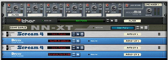
  1. Building upon the above example, at the bottom of the Combinator stack, holding Shift down, let’s add another Scream and Dr. Rex.
  2. Next, turn off the Damage parameter in the second Scream. Also, add a different loop into the second Dr.Rex device.
  3. The front panel with two scream and 2 Dr. Rex devices
    The front panel with two scream and 2 Dr. Rex devices
  4. Flip the rack to the back, and send the Audio from the Second Dr.Rex to the Second Scream, and send the Auto CV output from the second Scream to the CV 2 Modulation input on the Thor.
  5. Now we’ll have to set up Thor to also accept the second Dr.Rex CV source. In the MBRS section, enter the following:

    CV In 2: 66 > DelFBack

    CV In 2: 66 > Del ModAmt

  6. The MBRS settings in Thor
    The MBRS settings in Thor
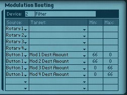
  7. Finally we need to use the Combinator button 1 as a switcher between the two CV sources. So in the Combinator’s Modulation Routing section, enter the following:

    Button 1 > Mod 1 Dest Amount: 66 / 0

    Button 1 > Mod 2 Dest Amount: 66 / 0

    Button 1 > Mod 3 Dest Amount: 0 / 66

    Button 1 > Mod 4 Dest Amount: 0 / 66

    Programming the Modulation Routings in the Combinator
    Programming the Modulation Routings in the Combinator

With this setup, Button 1 on the Combinator is used to switch between the 2 Scream CV sources (which in turn comes from the two Dr.Rex devices). Leaving button 1 off uses the first Scream device. Turning the button on turns off the first Scream CV source, and turns on the second Scream CV source. Note: it’s not actually the Scream that is turning off. We’re just bringing the amounts down to zero on the Thor programmer panel, which has the same effect.

It should also be noted that you can program a Rotary on the Combinator to cross-fade between the two CV sources, if you wish to have a fading effect between the two. Where you take this idea is really up to you.

Using Thor as an Audio/CV converter

Let’s say you don’t want to use the Scream, and instead want to use Thor as a “Auto CV output” or CV envelope follower. Here’s how you set that up.

  1. Starting from scratch, Create a Combinator and a 6:2 Line Mixer. Then holding shift down, create in order a Thor, NN-XT, and Dr.Rex device.
  2. Click the Show Programmer button in Thor, and turn off Oscillator 1, Bypass Filter 1, and click the “1” button next to the Filter 1 slot. Add a Low Pass Ladder Filter in the Filter 3 slot. Finally, click the Delay button to turn on the Global Delay.
  3. In the NN-XT open up the patch browser and navigate to the Factory Soundbank. Go to the NN-XT Sampler Patches > Synth Poly and open the Odd Poly patch.
  4. In the Dr.Rex device, open the Patch browser and in the Factory Soundbank, nagivate to Dr Rex Drum Loops and load the Hse40_RideBeat_130)eLAB.rx2 patch.
  5. We’re done with the front panel. Flip to the back of the rack, and let’s move on to routings. First, route the NN-XT’s 1/L and 2/R to the Audio In 1 and Audio In 2 on the Thor Audio Inputs, respectively. Then route the 1 Mono/Left and 2 Right from the Thor’s audio outputs to Channel 1 on the Line Mixer (left and Right, respectively).
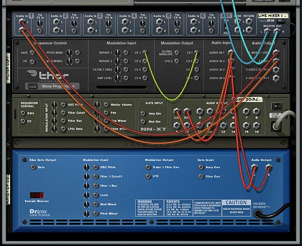
  6. This time, connect the Dr.Rex L & R audio outputs into Thor’s Audio Inputs (3 and 4, respectively). Then connect the CV 1 output to the CV 1 Modulation input, both input and output are on Thor, so yes you can route a CV out on Thor to a CV in on the same Thor.
  7. The back of the rack - routing Thor to work as an Auto CV envelope follower
    The back of the rack - routing Thor to work as an Auto CV envelope follower
  8. Flip the rack around and let’s set up the Thor Modulation Bus Routing Section (MBRS). Enter the following parameters on the left side of the bus:

    CV In 1: 66 > DelFBack

    CV In 1: 66 > Del ModAmt

    Enter the following parameters on the right side of the bus:

    Audio In1: 100 > Filt3 L.In

    Audio In2: 100 > Filt3 R.In

    Audio In3: 100 > CV Out1

    Audio In4: 100 > CV Out1

    The MBRS settings in Thor
    The MBRS settings in Thor

With this setup, the Auto CV is contained within Thor. The Thor is using the Audio from the Dr.Rex directly, and then converting the Audio source into a CV signal which is then sent back into Thor to affect the Delay Feedback and Delay Modulation Amount.

One note here: if you test out the sounds from the Thor CV setup versus the Scream CV setup, you’ll notice that the Thor CV is much smoother. I’m not sure why that is. It may be a difference in the way I’ve routed things, or a difference in how the Scream handles the Auto CV output feature. But there is definitely a difference in sound. Of course this could be pilot error and I may not have the connections set up correctly. I admit my mistakes all the time. But at least it gets you pretty close.

So any other ideas you have for using the Auto CV output on the Scream device or setting up Thor to convert an Audio signal into a CV signal? This is a very basic example, but it opens up a lot of potential with other sound sources / CV destinations. For example, if you have a CV destination that you want to track to the lead vocals in a song, you can do it easily. So what other possibilities are out there?

7 – Adjustable CV

Explore how to use Thor as a CV merger / splitter and Pass-Through, allowing you to set up the Combinator Rotaries so you can adjust CV levels and automate those CV changes. All of this without even breaking a sweat.

Let’s have the capability to freely adjust and automate some CV Trim Pots.

I knew that would get your attention. What? I can’t freely adjust and automate the CV trim pots on the back of the rack. What the hell is he talking about? Has he lost his mind.

Yes. I’ve lost my mind long ago. But I’ve recently found it and I’m here to try and provide a few workarounds to do things such as creating adjustable CV levels, as well as provide the ability to adjust merged and split CV sources. All without having to resort to the CV Merger/Splitter. Sound interesting? Well then let’s dig in. . .

When it comes to Thor, you’ve got a very powerful and, in my opinion, wonderfully versatile and variable sounding synth. But Thor can do a lot more than generate great synth sounds. It can perform a set of functions that no other device in the Reason arsenal can. In a previous tutorial I walked through various ways you could use Thor as an audio filter and explored a few practical uses of routing your audio through Thor. Here I’m going to explore how to use Thor as a CV merger / splitter, and furthermore, how using Thor can allow you to automate your CV trim pots, without even breaking a sweat.

The project files used for this tutorial can be downloaded here: adjustable-cv-examples. There are 6 Combinator Examples, outlining the types of tricks we’ll be doing with CV, Thor, and the Combinator Programming below. There is also the original sound source so you can compare that to all the other sounds in the 6 Combinator Examples. The Matrix tied to all the Combinators plays a single note “Drone” sound at 1/4 resolution. In order to test the examples, mute out the other channels in the main mixer except the one you are testing.

Using Thor as a CV Merger

  1. Create a Combinator, and inside the Combinator, create a 6:2 Line Mixer. Then holding shift down, create a Thor. Without holding shift down, create a Malstrom. Then once again, hold shift down and create a Subtractor.
  2. On the Subtractor, set Polyphony to 0, and press the Sync button on the LFO 1. Then duplicate the Subtractor 3 more times. On each new subtractor, select a different LFO waveform. You’ll now have 4 Subtractors with 4 different Waveforms.
  3. On the Malstrom, open the “Electric Yawn” patch under the Factory Soundbank (in the Malstrom Patches > FX folder). This is going to be our sound source.
  4. On the Thor, Initialize the Patch, and click the Show Programmer button. Turn off the Oscillator 1, and bypass Filter 1. Also click the “1” button next to Filter 1. Finally, add a Low Pass Ladder Filter into the Filter 3 slot. We’ll use 4 LFOs to affect the Filter 3 Frequency from the Thor, which in turn affects the Filtering of the Malstrom sound.
  5. Time to flip the rack around and do a little routing. Move the two audio plugs going into the Line Mixer, and plumb them into the Audio in 1 and 2 on the Thor inputs. Then plug the 1 Mono / Left and 2 Right outputs from the Thor into the Audio in on the Line Mixer’s first channel. Audio routing through Thor is setup.
  6. Next, on the back of the Subtractors, route the LFO 1 Output to the CV inputs on the back of the Thor; 1 for each of the 4 CV inputs on the back of the Thor.

    Merged CV Routing through Thor
    Merged CV Routing through Thor
  7. Flip the rack back to the front, and let’s move to the Thor’s Modulation Bus Routing Section (MBRS). On the right side of the mod bus, enter the following settings: Audio In1 > 100% > Filt3 L.In and on a second line on the right enter Audio In2 > 100% > Filt3 R.In. This sets up the Audio to be filtered through Thor.
  8. Next, on the left side of the MBRS, enter the following settings:
  9. CV In1 > 0 > Filt3 Freq.

    CV In2 > 0 > Filt3 Freq.

    CV In3 > 0 > Filt3 Freq.

    CV In4 > 0 > Filt3 Freq.

    Thor MBRS for the CV routings (left) and audio pass-through (right).
    Thor MBRS for the CV routings (left) and audio pass-through (right).
  10. Now let’s turn to the Combinator Programming. Let’s set up each Rotary to control the amount of CV applied to the Filter 3 Frequency. In this way, the Rotaries will work as the CV trim pots. So here’s where the magic happens. Set up the following modulation for the Thor:

    Rotary 1 > Mod 1 Dest Amount: 0 / 100

    Rotary 2 > Mod 2 Dest Amount: 0 / 100

    Rotary 3 > Mod 3 Dest Amount: 0 / 100

    Rotary 4 > Mod 4 Dest Amount: 0 / 100

    Combinator Programming
    Combinator Programming

This modulation setup means that you can control the Amount in the Thor Modulation Bus via the Rotary controls. It’s usually overlooked by many people. But at the bottom of the Thor’s Modulation Bus, after you scroll down through all of Thor’s parameters near the bottom lies the Modulation Destination Amount and Scaling Amount. In this way, you can control any one of the 13 modulation routings (amount and scaling).

To sum up, this Combinator we’ve created will use all 4 LFOs from the four Subtractors in unison to affect the Filter 3 Frequency of the Thor, which in turn affects the filtering of the sound source from the Malstrom. The true beauty of it all is that you can control the CV level using the Rotaries on the combinator. This works like a CV trim knob you’d find on the back of the rack.

Using Thor as a CV Pass-Through

Merging the CV signals and then controlling their level with multiple Rotaries on the Combinator are all well and good. But let’s say you don’t want to control any Thor parameters. What if you want to control an external CV source. For example, you want to control the “Shift” parameter on the Malstrom with a Subtractor LFO. This is pretty easy. Just route a CV connection from the Sub’s LFO to the Mal’s shift parameter on the back of the rack and you’re done. But you can’t control the Trim pot with this setup. So using the same kind of setup as above, here’s how you can use Thor as a Pass-Through for your CV source/destination, and at the same time tie the CV amount to a Combinator Rotary.

  1. Create a Combinator, and inside the Combinator, create a 6:2 Line Mixer. Then holding shift down, create a Thor. Without holding shift down, create a Malstrom. Then once again, hold shift down and create a Subtractor.
  2. On the Subtractor, set Polyphony to 0, and press the Sync button on the LFO 1. Select the Pulse Width waveform for the Subtractor.
  3. On the Malstrom, open the “Electric Yawn” patch under the Factory Soundbank (in the Malstrom Patches > FX folder). This is going to be our sound source.
  4. On the Thor, Initialize the Patch, and click the Show Programmer button. Turn off the Oscillator 1, and bypass Filter 1. Also click the “1” button next to Filter 1.
  5. Time to flip the rack around for our routing. On the back of the Subtractor, route the LFO 1 Output to the CV 1 Modulation Input on the back of the Thor; Then connect the CV 1 Modulation Output from Thor to the Shift Modulation Input on the Malstrom. Also turn the Shift Trim knob all the way right, so that it is completely controlled by the CV.
  6. Using Thor as a CV Pass-Through: Routing on the back of the rack
    Using Thor as a CV Pass-Through: Routing on the back of the rack
  7. Flip the rack back to the front, and let’s move to the Thor’s Modulation Bus Routing Section (MBRS). We only need one setting entered on the left side of the MBRS:
  8. CV In1 > 0 > CV Out1.

  9. Now we need to add one final programming setting on our Combinator. Open the Combinator’s Programmer, and set up Rotary 1 to control the amount of CV applied to the Shift parameter on the Malstrom. In this way, as before, the Rotary operates as the CV trim pot, moving from left (no CV applied) to fully right (100% CV applied). Set up the following modulation for the Thor:

    Rotary 1 > Mod 1 Dest Amount: 0 / 100

If you move the Rotary, you’ll hear the LFO  operating on the Shift parameter of the Malstrom. So now using this technique you can apply CV from any source to any device that has a CV input destination on the back of the rack, and also adjust the level of that CV source.

Note: if you are trying to control the Level parameter, it’s best to control your level from the Main mixer to which the sound source is connected. This way, when the Rotary is set all the way left (zero), the mixer’s channel fader will be used for the level. When all the way right (at 127), the Level is controlled 100% by CV. If, on the other hand, you try to control the level via the Malstrom’s Level CV, when the Rotary is at zero, no sound will be heard. When the Rotary is all the way right, you will hear 100% CV. So depending on what outcome you want, you may want to set this up one way or the other. The downside to routing CV from the Combinator to the Mixer’s Level CV destination is that you are setting up external routing from the Combinator. Not a problem if you save the file as an .rns instead of saving the Combi on its own. You can see this Level Pass-Through set up in one of the Combinators in the Project Files.

Using Thor as a CV Splitter

Next, we’re going to look at how you can split CV signals with Thor. This time, we’re going to send 3 CV signals to adjust 3 different CV destinations. Then we’re going to use the Combinator Rotaries to adjust the CV source level (thereby adjusting the CV amount applied to all 3 destinations at once).

  1. By now you should be getting used to the type of setup we’re using. This time we’ll create the Combinator, then inside create the Line Mixer, Thor, Malstrom (with Electric Yawn patch), and Subtractor (to use the LFO 1). Alternately, you can select and copy the Combinator from the previous example, since it already has this kind of setup created.
  2. Now we’ll flip to the back of the rack and connect the LFO1 Modulation output from the Subtractor to the CV 1 input on the Thor. Now, connect the Thor CV 1 output to the Malstrom Pitch CV input. Connect the Thor CV 2 output to the Malstrom Index CV input. Connect the Thor CV 3 output to the Malstrom Shift CV input. Finally, turn these three CV trim pots on the Malstrom all the way right.
  3. Using Thor as a CV Splitter: CV routing on the back of the rack
    Using Thor as a CV Splitter: CV routing on the back of the rack
  4. Flip the rack around again, and in the Thor MBRS, enter the following settings:
  5. CV1 > 0 > CV Out1.

    CV1 > 0 > CV Out2.

    CV1 > 0 > CV Out3.

  6. In the Combinator Programming, you can set it up 2 ways, depending. If you want to control all 3 parameters’ CV levels at once with a single Rotary, Select Rotary 1 as the source on 3 different programmer lines. Then create 3 different Destinations: Mod 1, Mod 2, and Mod 3 Dest Amount. Enter 0 and 100 for the Min / Max settings respectively. If, on the other hand, you want to have separate control over the 3 different parameters, You can change the Source so that Rotary 1 controls Mod 1 (Pitch), Rotary 2 controls Mod 2 (Index), and Rotary 3 controls Mod 3 (Shift). It all depends how you want things set up.

Note: I haven’t yet tried this, but I think you can invert the signal (just like the spider CV splitter has an “inverted” CV out). To do this in our setup above, you can set the min / max values from -100 to +100 respectively. This way, your Rotary knob will be at 0 when dead center. Moving the knob left will invert the CV signal, and moving the knob right will give a positive signal. Like I said, I haven’t tried it out, but I think I’m on solid ground here.

So there you have it. Thor can merge CV signals together, split CV signals to send the same signal to multiple destinations, and can be used as a pass-through for CV signals to affect other devices via CV. While you can do all of this with the Spider Merger/Splitter, the advantage Thor offers is that you can adjust the level of CV incoming from the source and applied to the destination, and automate this in the sequencer via the Rotaries on the Combinator. This is something that cannot be done using the Merger/Splitter alone. I hope this leads you into other avenues of exploration with Thor and CV modulation. If you have any other ideas that come to mind, please let me know. And if you have anything to add to this, please comment. I’d love to hear your thoughts.

6 – Vocoder Arp Machine

A very flexible Combinator mashup that plays an Arped up Thor run through a Vocoder. A second Thor is used to modulate the sound. Use this Combinator as a template to drop in your own Thor patches and then take it out for a spin at your next live gig. All the Combinator parameters are assigned to toy with the Arp / Vocoder settings. After all, the more flexible the Combinator is, the more use you will get out of it.

I was looking through eXode’s fabulous collection of free patches and combinators in his massive synthesis refill (available from the Propshop’s Free Refill Download Page – A must have for anyone who is looking for a great collection of new sounds!) when I came across a few patches that were hidden away with (arp) in parentheses after the patch names. Being one who loves a good arp sound I started to delve a little deeper into how it was put together. So this became the inspiration for this project. It fuses an arp with two thors — one for the modulation and another as the carrier, and both Thors feed through a Vocoder to the final output.

Now taking things a few steps further, I decided to deviate from what eXode did and add on a few modifications. Firstly, the sounds I used were completely my own (I didn’t want to copy eXode’s brilliant work). And I then took things another step further by assigning parameters to the Combinator rotaries and buttons. This way, you can use the Combi as a performance tool as well. And you can experiment with your own Thor sounds for the carrier and change the way the vocoder operates by toying with the Thor synth parameters, creating your own endless variety of Arp Vocoder machines.

So this is a bit of a mashup, being a Combinator that plays just fine as it is, or used as a template where you can drop in your own Thor patches. Finally, it can be used in live performance, since all the Combinator parameters are assigned for this purpose. After all, the more flexible the Combinator is, the more use you will get out of it.

The project files can be downloaded here: vocoder-arp. It contains an .rns file with a single Combinator which is pre-programmed to most of the major parameters you’ll need to adjust the Filter Frequency, Arp and Vocoder parameters.

Setting up the Vocoder Arp Template.

  1. First, create a Combinator, then inside the combinator create a 6:2 Line Mixer, Thor, RPG-8 Arpeggiator, BV512 Vocoder, and then holding Shift down (to disable auto routing), create another Thor. Flip the rack around and route the bottom-most Thor’s 1 Mono / Left Output to the Modulation input on the Vocoder. This is the basic setup for the arped-up vocoder. The first Thor in the Combi is the carrier, and an Arp is tied to this Thor. In other words, this is the main sound going into the Vocoder. The second Thor in the Combi is used to Modulate that Carrier sound through the Vocoder.
  2. Next, holding Shift down, create two Spider CV Merger/Spliters below the Combinator’s Line Mixer. Then hold Shift down and create a Matrix at the bottom of the stack. Set the steps to 4 and the resolution to 1/4th. Switch the Matrix mode to Curve, flip the rack around to the back and switch the curve mode to Bipolar. Then flip the rack around again and set up a curve pattern so that step 1 and 3 are +64 and step 2 and 4 are -64.
  3. The front of the Vocoder Arp with all devices
    The front of the Vocoder Arp with all devices
  4. Flip the rack around and on the first Spider connect the Arp Note CV out to Split A in and the Arp Gate CV out to Split B in. Connect one of the splits from Split A to the Carrier Thor’s CV in. Then connect the inverted split from Split A to the  Carrier Thor’s CV1 Modulation input. Connect one of the splits from Split B to the Carrier Thor’s Gate input, and another split from Split B to the Carrier Thor’s CV2 Modulation input.
  5. On the second Spider connect the Curve CV output from the Matrix to Split A’s input. Then connect one of the splits from Split A to the Split B input on the same Spider. Connect another split from Split A to the Vocoder Hold input. Connect the third split from Split A to the Carrier Thor’s CV3 Modulation input. Then connect the inverted split from Split A to the Arp’s Velocity CV in. on the Spider’s Split B, connect the inverted split to the Arp’s Octave Shift CV in. That just about does it for the CV routings. Luckily you can see the Combinator for yourself when you download the project files, because that was a mouthful. But it sounds more complex than it actually is.
  6. Moving to the Arp, and while you’re on the back of the rack, remove the CV cables from the Mod Wheel and Pitch Bend CV out. This way when you use the Pitch Bend, it will only affect the Thor Carrier’s Pitch Bend setting. Now flip the rack around again. Set up the Arp with an Octave Range of 2, and Insert set to Low. On the Vocoder, set the Attack to 8.
  7. The back of the rack with all the routings in place
    The back of the rack with all the routings in place
  8. Now we move to the Combinator programming. Click the Show Programmer button and enter the following settings:

    For the Thor Carrier:

    Performance Controllers > uncheck the Mod Wheel

    Rotary 1 > Filter 1 Freq: 0 / 127

    Rotary 2 > Amp Env Attack: 0 / 25

    Rotary 2 > Amp Env Decay: 50 / 27

    Rotary 2 > Amp Env Release: 18 / 27

    Button 1 > Filter 1 Env Amount: 28 / 100

    Button 4 > Delay Sync: 0 / 1

    For the Arp:

    Rotary 3 > Gate Length: 10 / 115

    Mod.W > Synced Rate: 5 / 15

    For the Vocoder:

    Rotary 4 > Shift: -20 / 20

    Rotary 4 > Decay: 80 / 127

    Button 2 > Band Count: 3 / 1

    For the Thor Modulator:

    Performance Controllers > uncheck the Pitch Bend and Mod Wheel

    For the Matrix:

    Button 3 > Pattern Select: -1 / 0

  9. The Combi's mod programming for the Thor Carrier (left) and Arp (Right)
    The Combi's mod programming for the Thor Carrier (left) and Arp (Right)
    The Combi's mod programming for the Vocoder (left) and Matrix (right)
    The Combi's mod programming for the Vocoder (left) and Matrix (right)
  10. Now flip the rack to the front now, and load up your favorite patch in the Thor carrier. Usually a bright lead will work best, but experiment with any sound you like. You can take a look at how I programmed the Thor in the image below. I won’t go into all the settings that were used. You can pretty much see them here. However, there are some core settings that are needed in the Modulation Bus Routing Section (MBRS) in order to have the Combinator function properly. On the right side of the Bus, create the following routings*:

    CV In1: -32 > Del Rate

    CV In2: -56 > Del ModAmt

    CV In3: 50 > Amp Pan

  11. The front of the Thor Carrier
    The front of the Thor Carrier
  12. Add a matrix below the Combinator so that it is playing the Combi. Then enter a pattern and hit play. This tests out the sounds of the Combi as you experiment with your Carrier and Modulator. For the modulator, you usually want something atonal or heavy on the noise. Unmusical is best. Droning is perfect to affect your carrier signal. This is the fun part where you toy with the Thor until you get something you like. The nice thing is that you have a wide variety of sounds to choose from using the Thor synth.

An explanation of the Combinator Programming

Pitch Bend: This affects only the Thor Carrier as you would expect a pitch bend to operate.

Mod Wheel: The Mod Wheel controls the Arp’s Synched Rate from 1/4 to 1/128th. You can use this as a performance controller to create some interesting arp variations. Let your ears be your guide on this one.

Rotary 1: This controls the full range of the Filter 1 Frequency from the Thor Carrier. Fully left and the filter is closed, fully right and the filter is fully open.

Rotary 2: This controls the Amp’s Attack, Decay, and Release from the Thor Carrier. Fully left and you’ll have very short ADR setting. Fully right and you’ll have much longer ADR settings

Rotary 3: This controls the Gate Length on the Arp. This is one of my favorite settings to play with because it can drastically alter the sounds coming from the Arp. Fully left and you have very short note lengths where the notes are staccato. Turn the knob fully right and you’ll have very long notes – to the point where the notes blend into each other much more smoothly (legato).

Rotary 4: This controls the Shift and Decay of the Vocoder at the same time, affecting the phase of the sounds you hear. This actually shifts the filters of the Vocoder’s Carrier signal down (turning the knob left) or up (turning the knob right). This can be a fun parameter to play with, and you’ll have to experiment to hear what sounds pleasant to you.

Button 1: This controls the filter envelope for the Thor Carrier’s Filter 1. Use it as a sound mode switch, and as with the Rotary 4, you’ll have to hear what sounds pleasant to your ears.

Button 2: This adjusts the band count of the Vocoder. When off, Vocoder has 32 bands. When turned on, the Vocoder has  8 bands. One note about this button: it takes a little time to catch up with itself when you alter the bands. So this may not be great for performance, and you might want to keep this button either on or off. But it’s great fun to test out your sounds through different band counts. If you don’t like these settings, you can change them in the Combinator’s Programmer to switch between any 2 bands you like.

Button 3: For lack of a better word, I named this button “Slider” — as it sounds like the notes from the Arp are being slid on the last beat of the bar. In addition, the Slider button will Pan the sound from left to right in the stereo field based on the Panning settings that were set up in the Carrier Thor’s MBRS. Remember that CV3 in we set up in the Carrier Thor? That’s affecting the Pan of the signal. In addition, the Matrix we placed at the bottom of the Combinator Device Stack is waving the sound up and down like a pulse wave. With a resolution of 1/4, the signal is synched to the 4 beats of a 4/4 tempo. But the Slider does a bit more than that. It also controls the Hold parameter of the Vocoder via CV. This means that on the fourth beat of the bar, the Vocoder is held for the duration of that last beat (one full 1/4 note). Finally, it also controls the Velocity and Octave Shift of the Arp. Yep. One of those spiders and the matrix were set up to perform a simple switch. But I thought it was a pretty cool way to affect the signal. When you turn the button on, it starts up the Matrix pattern to control everything via CV. When you turn it off, the Matrix doesn’t play any pattern at all, essentially shutting down the CV triggers.

Button 4: Finally, we have a simple switch which either keeps the Global delay of the Thor Carrier free running (when left off), or synched (turned on).


* One note about switching the Carrier Thor’s patch. If you switch the patch, you’ll have to remap the settings in the Modulation Bus section for the CV1, CV2, and CV3 sources (all the settings on the right side of the Modulation Bus section). Otherwise, the Delay and Slider functions won’t work properly. Alternatively, you don’t have to switch the patch at all. You can play with the settings in the note / global sections of the Thor until you come up with a sound you like. Point is that since this Combinator is so heavily programmed, switching patches requires a little more tweaking than normal.

Switching patches in the Modulator Thor won’t require any remapping because none of its parameters are used externally.

Any thoughts on this setup? Any ways you can see to improve it? Let me know what you think. . .